External sails
Updated November 23, 2020
------------------ WORK IN PROGRESS ------------------
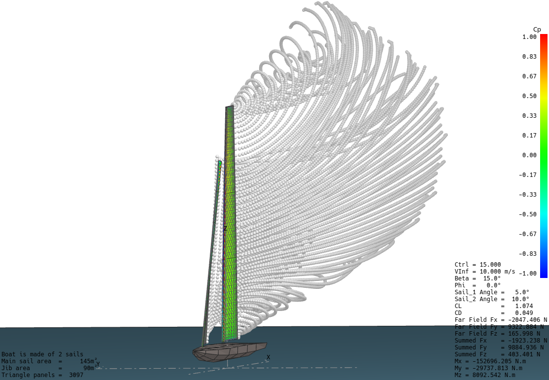
AC75 type boat with its vortex particle wake
External sails
flow5 offers the option to import and analyze sails defined in external CAD systems. The preferred import formats are STEP and STL, the main difference being that the surface mesh is generated in flow5 in the first case, and in the CAD system in the second case. In either case, flow5 expects that the imported sail is either a thin surface or a closed volume. As of v7.01 beta 18, flow5 cannot handle mixed configurations.
Two types of meta-data which are not present in either of the import formats are required by flow5 to perform the analyses.
- The first is the location of the sail's trailing edge. This information is required to implement the Kutta condition, without which the wake cannot be defined and the lift and induced drag cannot be calculated. .
- The other is the location of the head, tack, peak and clew points, which are used to define the luff axis and the trailing edge.
It is possible to define boats combining internal flow5 type sails and imported sails.
Back to top
Sails from CAD models
Thin sails
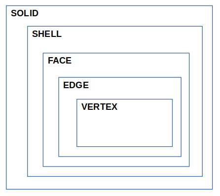
flow5 expects the geometry to be defined either as a SHELL, i.e. as an assembly of FACEs, or as a single FACE. The SHELL structure ensures that- all FACEs have been stitched together and share a common orientation, i.e. the FACE normal vectors point in the same direction;
- the edges are shared by the FACEs which allows their surface meshes to be connected.
Thick sails
flow5 expects the geometry to be defined as a single volume bounded by a SHELL. The volume should not be self-intersecting, and the FACE normals should point outwards. The SHELL structure is recommended for the same reasons as in the case of the thin surface sail.It is not required that the STEP file contains the SOLID structure, which will be unused and ignored.
Notes
- The preferred import format is STEP; IGES and BREP are recognized but have not been tested as of beta 18.
- The geometry defined in the CAD file is a dead surface so that its shape cannot be modified in flow5. The only possible modifications are translation, scaling and rotation.
- It is strongly recommended to simplify and clean the CAD model before importing it into flow5. The main thing is to remove all small EDGEs and FACEs. This will greatly simplify the task of building the mesh and improve its quality
Mesh
Once imported successfully the SHELL can be meshed with flow5's internal surface mesher. From that point on, the process is the same as for a sail defined by an external STL mesh.
Back to topSails from STL meshes
The STL standard
Sails defined by imported stereolithography meshes can be imported into flow5. As the acronym suggests, STL files are essentially intended for the exchange of models for 3d printing. However, there is apparently no other universally accepted file format for surface meshes, so that the STL format has become the usual standard. The advantage of the format is that it is ubiquitous and versatile. It is therefore the format recognized by flow5 to import the surface meshes.
The only information contained in the STL file is the position of each triangle's vertices and its normal. It does not contain any meta data, or any information on mesh connections. All the additional information required to define a geometry and run an analysis needs therefore to be reconstructed in flow5, either automatically or manually as explained hereafter.
Mesh quality
Since flow5 is not intended to be CAD software, it does not offer any significant tool to correct, heal or improve the mesh. It is therefore important that the external STL mesh should be of a quality acceptable as-is for a panel analysis, i.e.:
- The union of triangles should define one or more closed non-intersecting volumes.
- All triangle normals should be pointing towards the outside of the volumes.
- The mesh should not contain any duplicate triangles.
- The mesh should not contain any null triangle, i.e. with a zero or a very small area.
- Adjacent triangles should be of comparable sizes; this is not strictly compulsory, but will contribute to improve the precision of the results.
- Triangles should be oriented positively, i.e. the vertices should be ordered in counter clock-wise order around the normal using the right hand rule; the program will automatically attempt to correct any triangle with wrong orientation.
Element connections
The analysis requires that the mesh elements be connected, i.e. that each triangle "knows" with which other triangles it shares its edges, and that each node "knows" of which triangles it is a vertex. This information is not contained in the STL file and is reconstructed in flow5.
These connections are necessary to compute the pressure coefficients on the panels.
Analyses
There is no restriction in flow5 to the use of externally defined sails which once imported are handled as the other internal sail types.
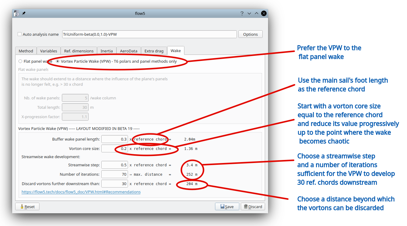
The recommended analysis type is the triangular uniform method combined with a Vortex Particle wake (VPW). The VPW avoids numerical issues linked to the potential interference of wake panels shedded by the jib with the main sail's panels. The recommended settings for the VPW are similar to those made for the analysis of airplanes. The first value for the vorton core size should be of the order of magnitude of the sail's streamwise length.
Back to top
Step by step
Import from an STL file
Open the boat editor, then in the menu "Add sail" select "from STL file".

This will open the STL reader interface.
The length unit is not part of the STL format. If it is known, select the length unit with which the file was written, otherwise select a large unit, typically meters. The model may be scaled down at a later stage if necessary.
Reading for instance in millimeters a file written in meters will cause triangles to be of a very small size which could cause issues when scaling up the model. In such a case, it is recommended to restart the import process using meters.
Click on "Import file", select the file and check the result in the text output window.
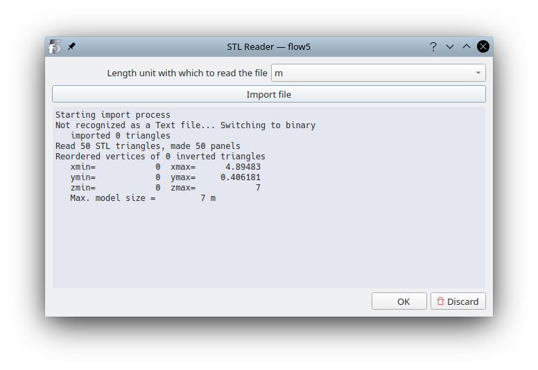
The only check made during the import process is the verification and eventual correction of the triangles' orientation.
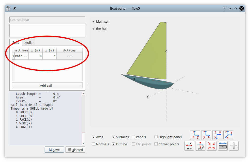
Once imported, the sail shows up in the 3d view. Use the table entries to position the sail on the boat.
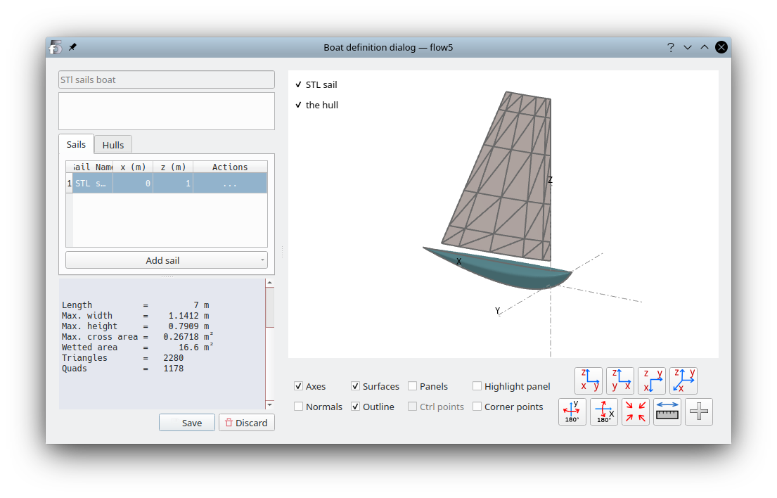
In the "Actions" column, select "Edit" to open the STL sail editor.
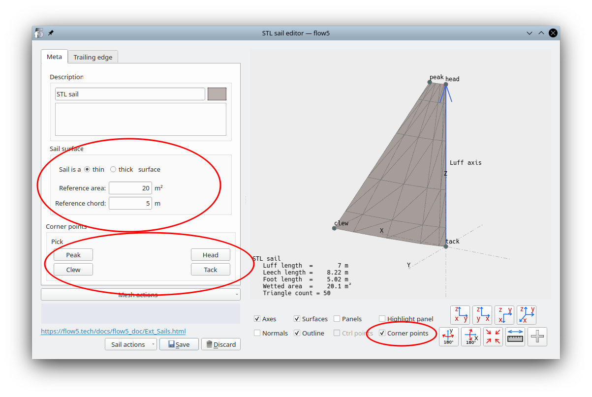
The first step is to define the meta-data which is not present in the STEP file:
- select whether this sail should be understood as a thin or thick sail,
- define the reference area and chord; these values will be used later in the analyses respectively for the calculation of the lift and drag coefficients, and to define the VPW,
- click on one of the four buttons "peak", "clew", "head", "tack"; the button will remain selected; then click on the corresponding point in the 3d view. In the case of a CAD-type sail, the points which can be selected are the shape's VERTICES. In the case of an STL-type sail, the triangle vertices can be selected.
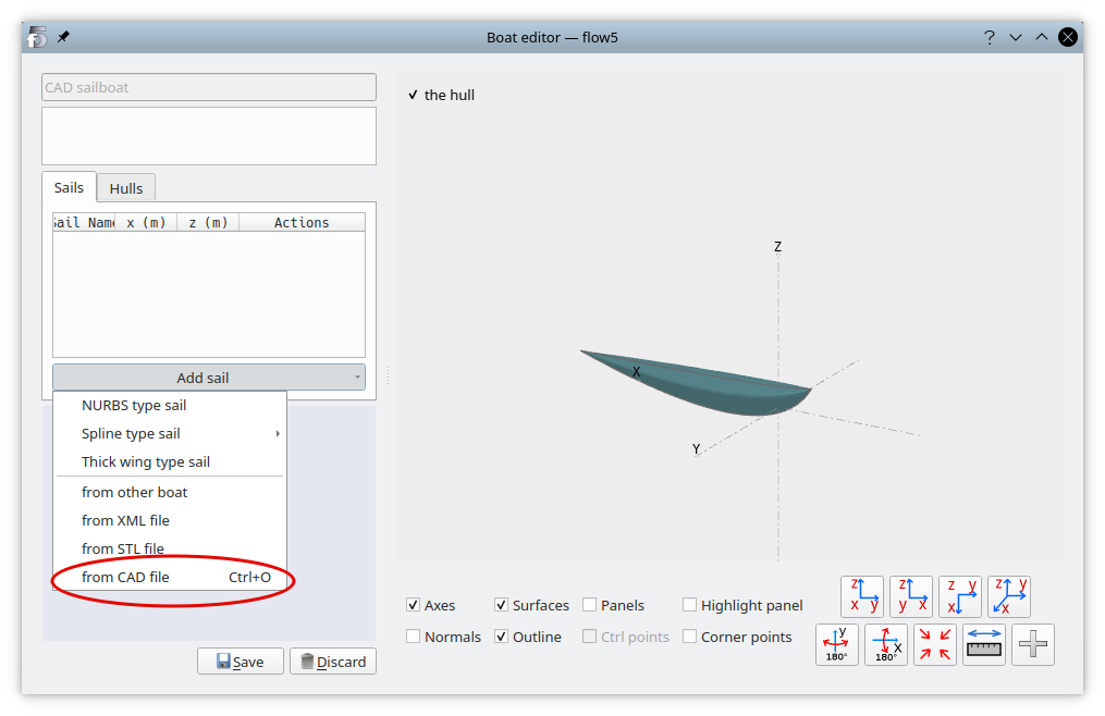
Import from a CAD file
Open the boat editor, then in the menu "Add sail" select "from CAD file". This will open the import interface.
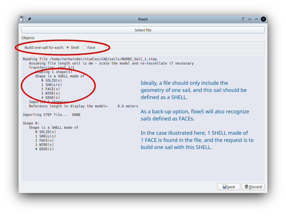
Each sail should ideally be defined in its own file. As a back-up option, flow5 can import multiple sails defined in a single file. In this case, it is required to specify whether flow5 should build one sail for each SHELL found in the file, or for each FACE.
Exit the import interface to return to the boat editor. Use the fields of the part table above the menu to give the sail a name and to position it relative to the boat.
Finally click on the three dots in the third column and select "Edit" to open the CAD-sail editor.
Define the meta-data as in the case of the STL file.Once this is done, move on to the mesh tab.
Mesh
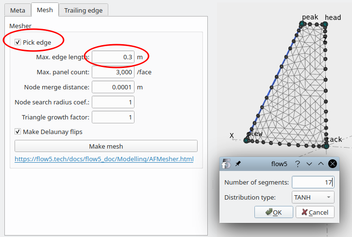
Activate the checkbox "Pick edge", then click on each of the edges in turn to set their nodes.
Define a max edge length for the triangles. To obtain a mesh of good quality, this length should be the in same order of magnitude as the distance between two edge nodes.
Ideally the mesh should be denser at the locations of high pressure gradients, i.e. the corner points and the edges.
Click "Make mesh" to generate the mesh.
The next step is to identify the panels which are part of the sail's trailing edge.
Trailing edges
The process to identify the trailing edge panels depends on whether the sail is a thin or thick surface.
In both cases however the first step is to request that the mesh be connected, i.e. that each panel "knows" which other panels are its neighbours, and that each node "knows" of which triangle it is a vertex.
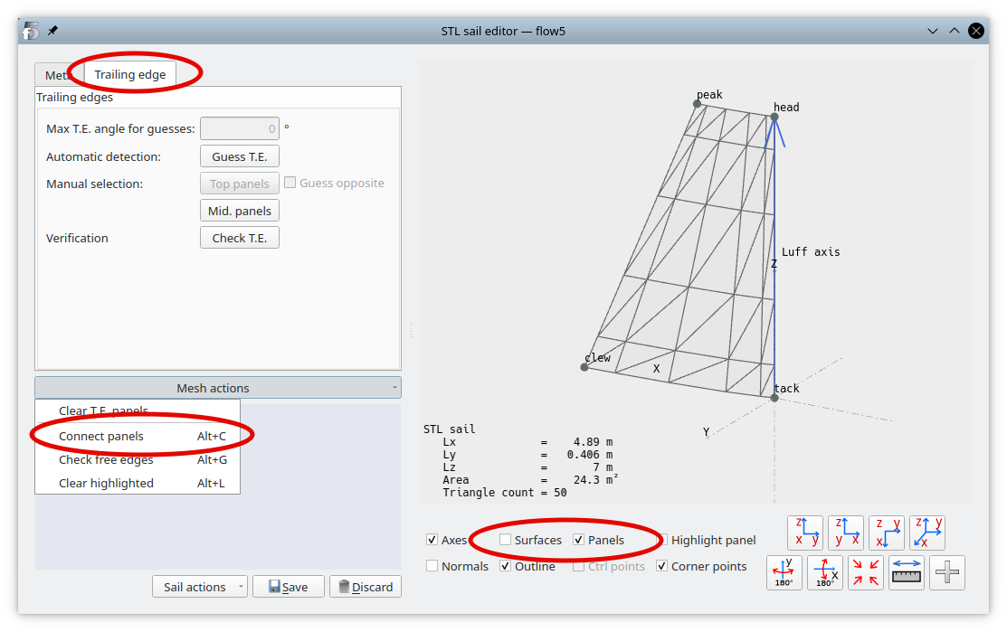
Move to the "Trailing edge" tab, and in the 3d view's controls, deselect "Surfaces" and select "Panels".
In the "Mesh actions" menu, select "Connect panels", and wait for the message "Connecting panels... ... done".
Thin sail type
To guess the trailing edges in the case of a thin sail, flow5- builds the free edges, i.e. the set of edges which only belong to one triangular panel,
- identifies the sets of free edges which link the clew to the peak, and selects the shortest path
- selects all the panels which have an edge belonging to this shortest path
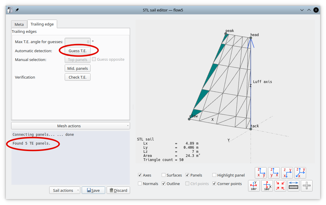
Click "Guess T.E."; the trailing edge panels will turn to dark green in the 3d view. As a back-up option, manual corrections can be made to the selection by activating the "Mid. panels" button and clicking on the panels one by one in the 3d view.
Thick sail type
To guess the trailing edges in the case of a thick sail, flow5 searches for all pairs of connected triangles such that the angle between their opposite normals is less than the specified threshold angle.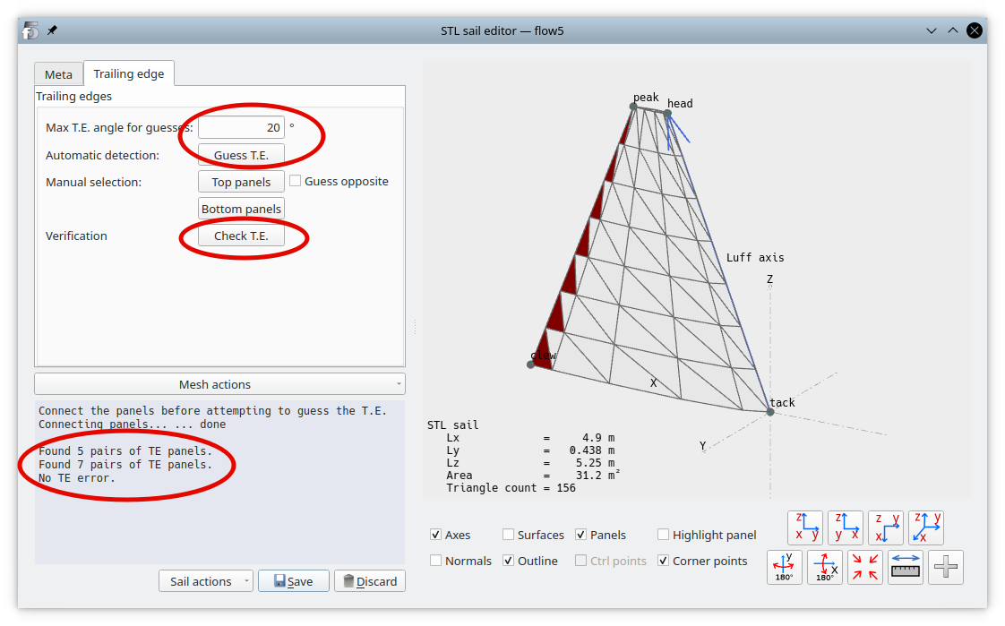
Start with a low value for the threshold angle, and click "Guess T.E."; the trailing edge panels will turn to dark green on the port side and to dark red on the starboard side.
This automatic process may also select unwanted leading edge panels. Manual corrections can be made to the selection by activating the "Top panels" or "Bottom panels" buttons and clicking on the panels one by one in the 3d view to toggle their selection. If "Guess opposite" is activated, flow5 will attempt to select the trailing panel on the sail's opposite side, within the limit of the threshold angle.
Note that each T.E. panel must be connected to one and only one opposite side T.E. panel. Click "Check T.E." to verify that the selection meets this requirement.
Next steps
The sail is ready to use. Save the changes and exit the editor.
Proceed to define and run an analysis as for internal type sails.
Recommendations for the VPW settings