
Surface mesher
Updated September 27, 2020
------------------ WORK IN PROGRESS ------------------
Surface mesh requirements
Thick surfaces
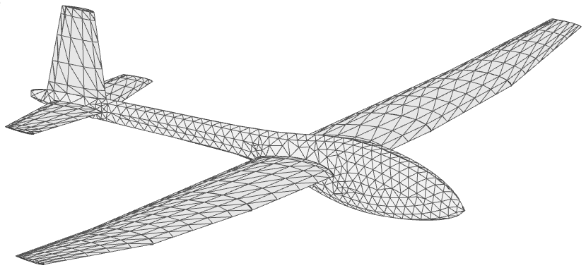
The main compulsory requirement of a boundary element method (BEM) such as the panel methods implemented in flow5 is that the surfaces form one or more closed, i.e. watertight, non-intersecting volumes.
These surfaces are defined numerically by a set of panel elements which cover the entirety of the surfaces. These elements can be flat quadrilaterals or triangles. The latter option is recommended for several reasons:
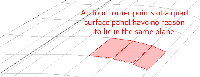
- Triangles can cover any 3d surface without gaps at the edges, whereas flat quadrilaterals cannot achieve the same result in general cases.
- Triangle elements offer the possibility to use higher order Galerkin methods.
- Triangle surface meshes are easier to construct than quad surface meshes.
Thin surfaces
Thin surfaces can be viewed as volumes of infinitesimal thickness and are therefore closed by construction. There are no special requirements on the mesh of thin surfaces, except for the general considerations on element quality.
Note that there is no built-in algorithm to connect thin wings to a fuselage.
Mesh density
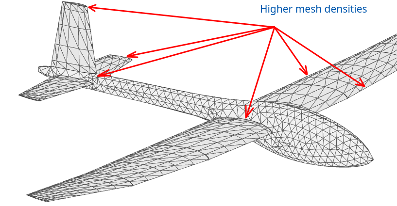
By nature, the uniform panel methods assume that the doublet densities are uniform over the surface of each surface panel. It is therefore important that elements should be sufficiently small so that this approximation is valid.
As a consequence, higher densities of smaller surface elements will be recommended at locations where the pressure gradient is expected to be important. This is typically the case at locations such as the leading and trailing edges, at the wing tips, and more generally at any location with significant variations of the local geometry.
Linear methods will also be more precise if these recommendations are satisfied.
Element quality
The quality of a triangle is usually evaluated by some measure of its deviation from the ideal equilateral triangle. flow5 uses the measures recommended by J. R. Shewchuk. Cf. "Delaunay Refinement Algorithms for Triangular Mesh Generation", Jonathan Richard Shewchuk, May 21, 2001.
Triangles with poor quality, i.e. ratio of circumradius to shortest element edge greater than sqrt(2) are denoted as "skinny" elements.
As it turns out, the panel methods using triangles are resilient and tolerant to the lack of quality of the elements, providing that the mesh density meets the requirements of the preceding paragraph.
Element connections and free edges
Free edges
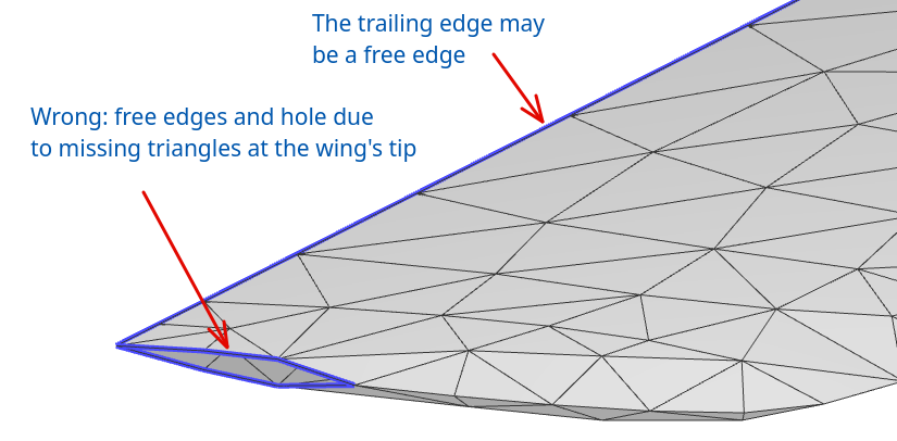
To form a close volume, all triangles should be connected to two other triangles, or in other words each edge should be shared by two and only two triangles. The edge of a triangle which is not shared with another triangle is a free edge.
If located elsewhere than at the trailing edges, free edges are an indicator of incorrect mesh construction. For flow5 type planes, i.e. not defined by external STL meshes, the top and bottom TE are not connected and therefore are free edges. These are the only free edges which should remain in the model.
The identification of free edges requires that triangles have been connected.
Watertightness
If the mesh is not watertight, i.e. does not form a closed volume, the results of the analysis will not be valid. flow5 however does not check watertightness and will therefore produce wrong results notwhithstanding. It is therefore a good precaution to check the volumes before running an analysis.
Back to top
Surface mesher
Surface mesh algorithms
The surface mesh algorithms fall into two categories:
- Parametric space meshers, where the mesh is first built in the topological space in which the surfaces are defined, before being converted into geometric space.
- Advancing front meshers, where the mesh is built incrementally starting at the edges.
CAD model preparation
Model import
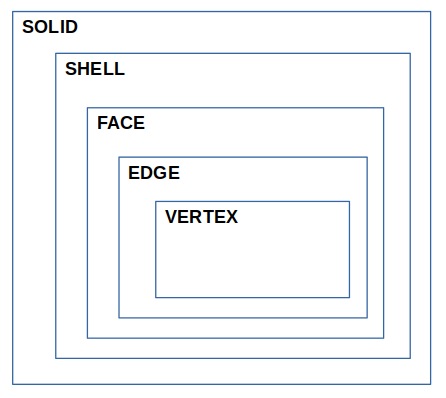
flow5 meshes independently each FACE of each imported SHELL. As a consequence, elements may not always be connected at the shared edges of faces. This will require manual correction if it occurs.
The simplification of the model in the CAD software before it is imported into flow5 is an essential step to achieve surface meshes of good quality and reasonable sizes. The main points which can cause mesh issues are:
- small faces
- small edges
- gaps between wires
All faces of the CAD model should be oriented positively such that the normals of the faces point towards the outside of the volume.
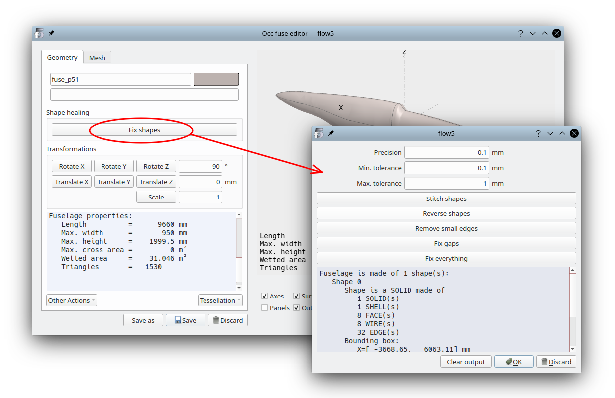
Shape healing
flow5 offers some limited options to heal the model, but as of v7.01 beta 15 these options remain experimental. It is therefore strongly recommended to perform this preparation of the model in the CAD software.
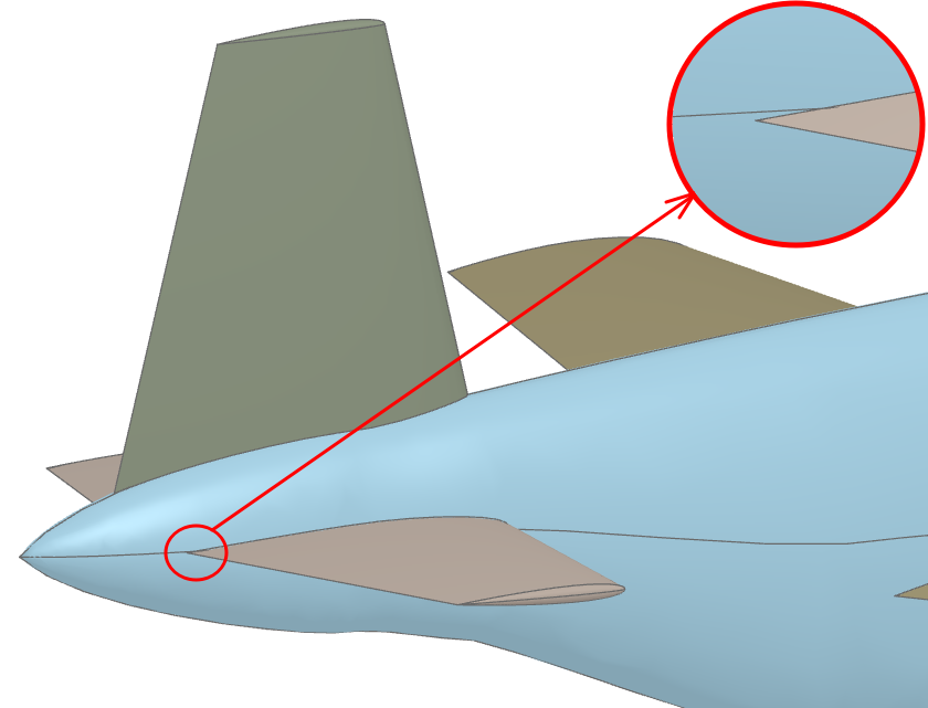
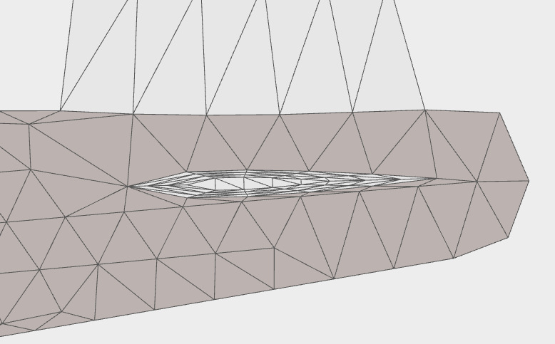
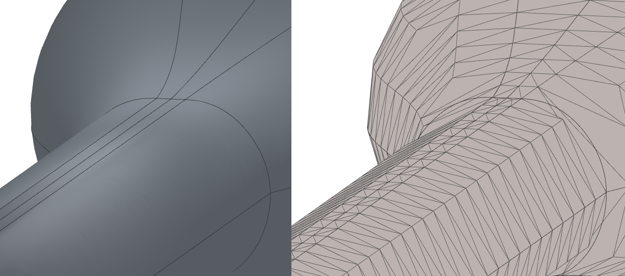
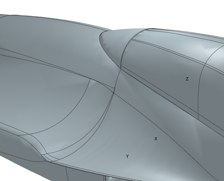
Model assembly and small EDGEs
It is recommended in such a case to modify either the wing's position or the fuselage's geometry to eliminate the small feature. A small geometrical modification should be of no consequence to the results.
There will be several benefits to this cleaning of the geometry:
- it facilitates the task of the mesher, and increases its chances of achieving a valid surface mesh;
- it helps improves the quality of the triangles and the accuracy of the analysis results;
- it reduces the number of surface elements and the analysis times.
Back to top
Step by step
Mesh parameters
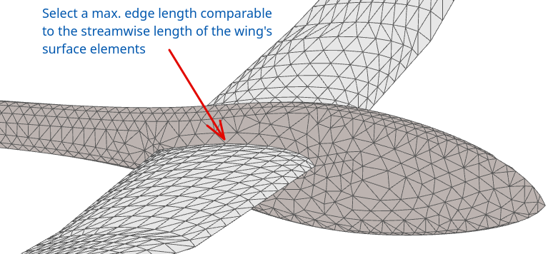
Once the fuselage's SHELL(s) have been cut by the wing shapes in the "Assembly" tab (Ctrl+3), move to the "Fuse mesh" tab (Ctrl+4).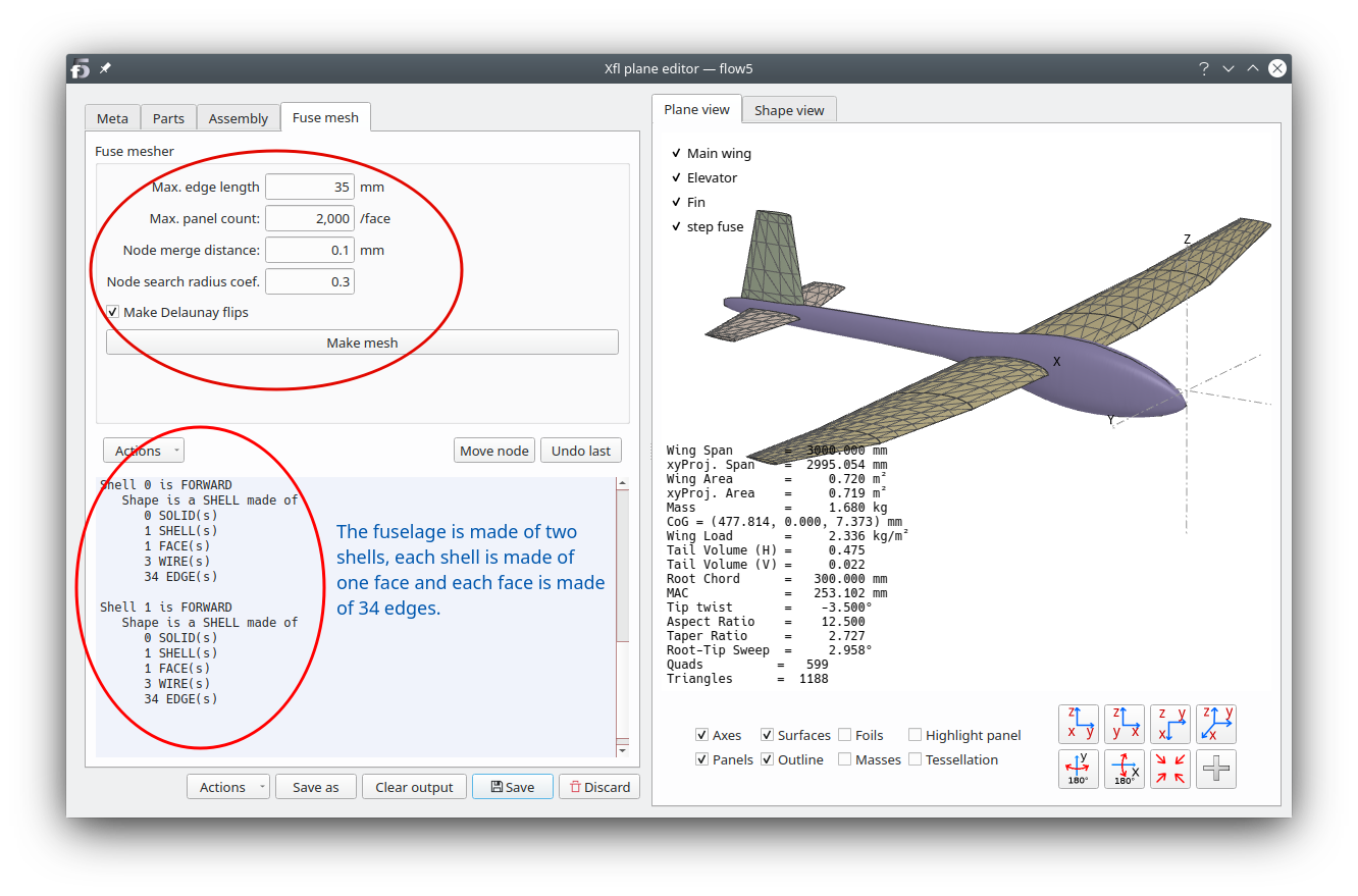
To facilitate the mesh operations, select a length comparable to the streamwise length of the wing elements.
Max. panel count: The number of triangle elements on each FACE will not exceed this value; this is meant to set a limit on the duration of the mesh operation. If the limit is reached on one FACE, the mesher will interrupt the process for this FACE and move on to the next.
Node merge distance Vertices closer than this length will be merged at their mid-point; this is to correct geometric precision errors at edges between faces. Recommendation: 0.1 mm.
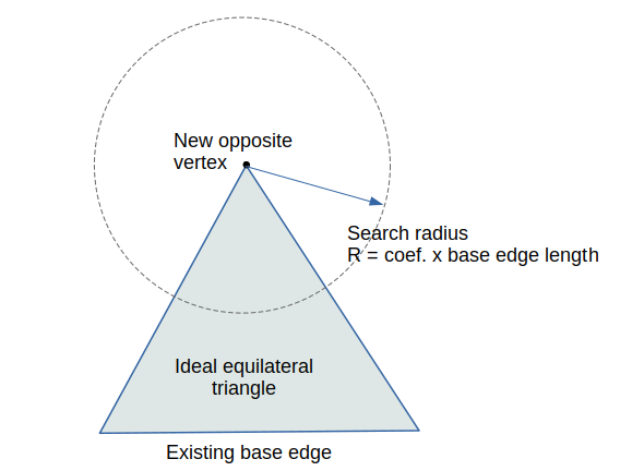
Node search radius coef. This parameter controls the growth of the element size. The surface mesher first builds an ideal equilateral triangle on an existing base segment, then searches for a close node within the circle around the opposite vertex. The radius of the circle is the coefficient times the length of the base segment. If an existing node is found, the vertex is merged with this node.
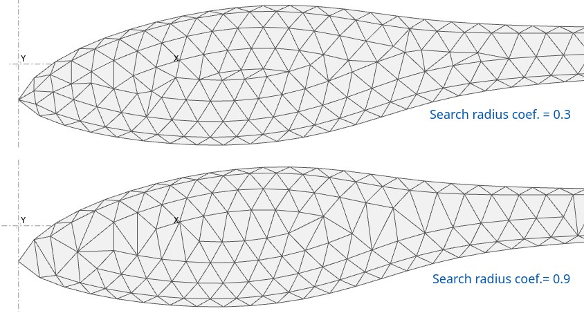
A small value will lead to a mesh of regular size, but can cause triangles to be distorted where opposite sides of the advancing front meet.
A larger value will lead to a less precise modelling of the FACE's geometry.
Recommendation: 0.3 < Coefficient < 1.
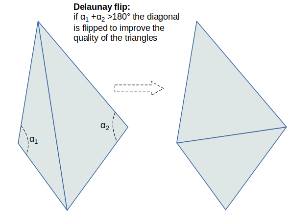
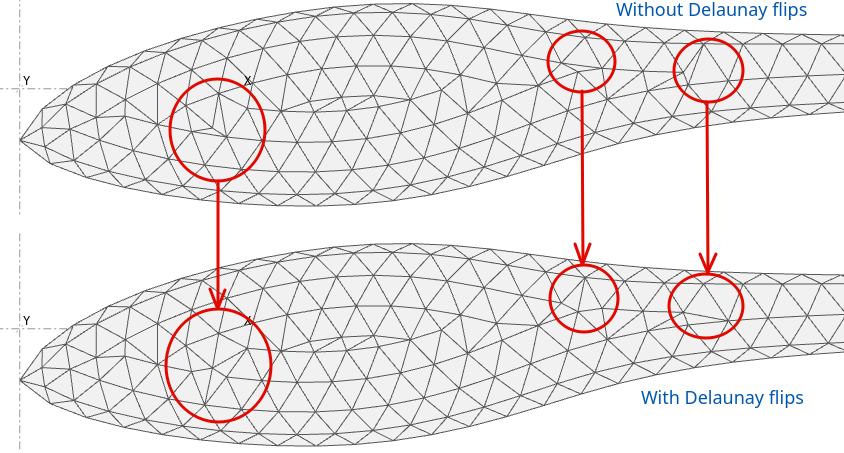
Delaunay flips: If activated Delaunay flips will be performed at the end of the mesh process.
Recommendation: Activate.
Animation
This feature was primarily implemented to debug the advancing front mesher, but can be used to understand and correct meshing issues.
Launch the debug mesher using the context menu command Active plane/Fuse/Fuse mesher or with the shortcut Ctrl+M.
The interface can also be opened from the "Fuse mesh" tab in the plane editor.
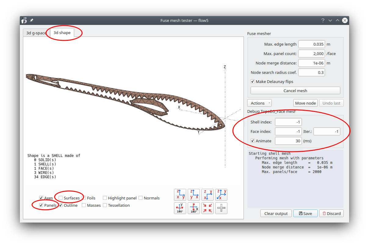
- Select the "Shape view" in the top left corner.
- Select the display of panels and deselect the surfaces.
- Enter the index of the SHELL to mesh, or -1 to mesh them all; indexes are zero-based.
- Enter the index of the SHELL's FACE to mesh, or -1 to mesh them all.
- Enter a positive number of iterations to interrupt the process once this number of triangles is reached.
- Activate "Animate" and select the refresh time interval for the animation.
- Click on the "Make mesh" button.
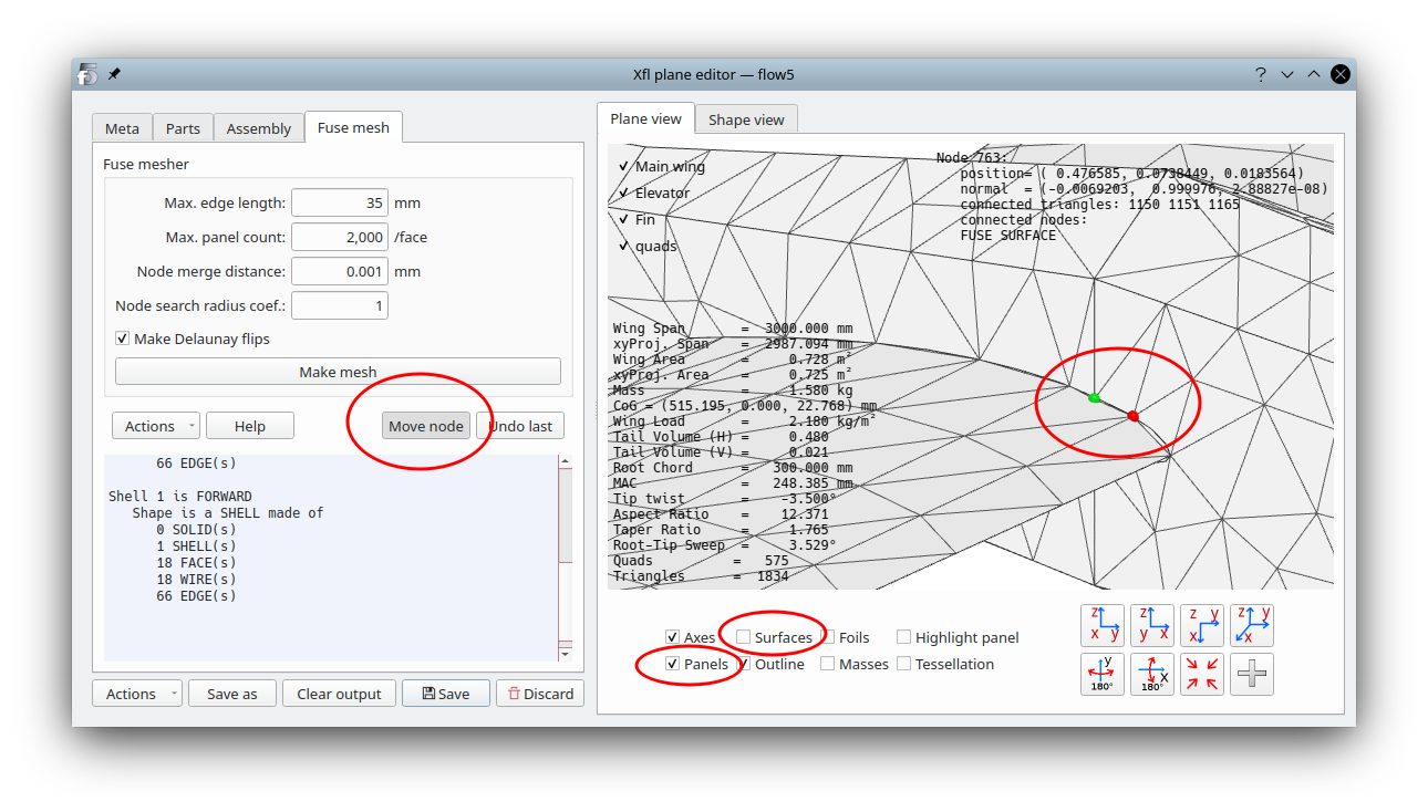
Manual mesh corrections
As of flow5 v7.01 beta 14, the only possibility to correct the mesh is to move a node to another node's location. This is intended:- to enable manual connections of the fuselage nodes to the wing nodes
- to enable manual connections of the triangles of adjacent fuselage faces
- to enable removal of incorrect elements which can typically be generated at a fuselage node and tip
- click the "Move node" button which will remain checked until clicked again or until the "Escape" key is typed;
- move the mouse in the 3d view and click on the node to move; once clicked it will be highlighted in green;
- click on the destination node; this must be a node adjacent to the first one
Mesh checks
Element geometry
flow5 has some built in tools to check the element quality. The tools can be accessed in the "Actions" button.
However experience so far has shown that triangles are not required to be as much of regular shape as in the case of a finite element analysis for instance. The main objective should be to ensure that triangles are not too skinny so that the pressure gradient and doublet density can be considered to be uniform over the surface of the element.
Closed non intersecting volumes and free edges
To ensure that the requirements of the BEM theory are met, it is important to verify the absence and of holes in the mesh as a final check.
The only tool available to this end in flow5 is the display of free edges. To display the free edges:
- In the "Actions" button's menu, request "Connect panels" and wait for the message "Connecting panels... ... done" to appear in the output window
- Request next "Check free edges"
The only edges if any should be located at the TE and at the wing tips.
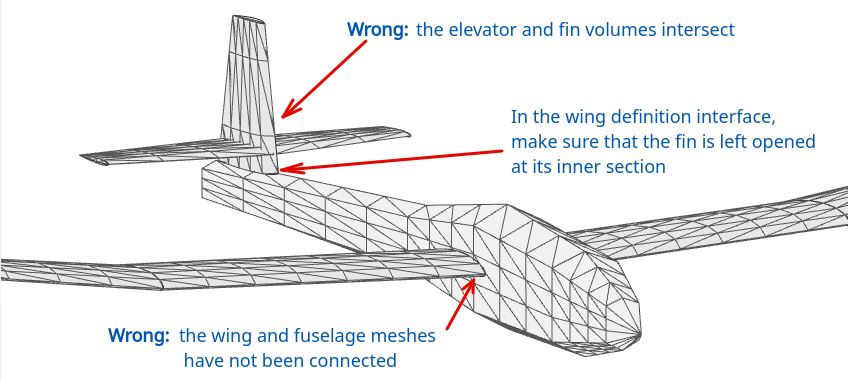
Volume collisions
- when two wings intersect
- when the fuselage has not been cut by the wing objects
- when the fin is connected to the fuselage and has been left closed at its inner section
Back to top