
Sail analyses
Updated November 23, 2020
------------------ WORK IN PROGRESS ------------------
Background
The sail analysis module implemented in flow5 uses the same panel code solver as the airplane module, while its user interface is similar to that of the sail7 prototype. It is recommended to experiment with sail7 before purchasing flow5 to understand the philosophy and general mechanismn of the sail analysis module.
The design intent of the sail module is to
- take advantage of the developments made for the airplane module to offer a tool to analyse sails at low additional costs,
- provide the user with the interfaces to perform sensitivity analyses using either the GUI or though script exectutions,
- offer a posiibility to import and analyse quickly sails designed in external CAD software.
Only the triangular panel methods have been activated in the sail module. The quad panel method and the VLM have been disabled due to their lesser versatililty, and because they do not offer any signficant advantage over the triangular panel methods. This in return allows for a more simple and robust code, without any functional restriction.
The ground effect due to the presence of the water's surface is activated by default.
Notes:- Due to the possibility of intersections of the wake panels shed by the sails, the Vortex Particle Wake (VPW) should be preferred to the flat panel wake representation, despite its greater computational cost.
- The analyses are inviscid, with the possibility of including additional user-defined extra drag. As of v7.01 beta 18, there is no experimental or numerical validation specific to the sail module.
- The hulls are not taken into account in the analyses. The reason is that no fast and convenient way has been found to model the intersection of the water surface and the hull whatever the boat's heeling.
- As of v7.01 beta 18, the sail analysis module has not yet reached the maturity and robustness of the plane analysis module. The beta phase has been extended by an additional month until end of November 2020 to bring it to the level of the rest of the application.
Back to top
Sail modelling
flow5 proposes several internal representions to model sails, and offers the option to import the sail definitions from external CAD and STL files. The intent is to enable quick sail design and modifications for parametric studies and sensitivity analyses.Nurbs type sails
In this representation, the sail is defined by a NURBS surface.
The NURBS geometry is defined by sets of control points which can be arranged manually in the graphical user interface, or imported from an XML file.
The main advantage of the NURBS model is its versatility and the C2 continuity of the surface.
Spline type sails
As an alternative to NURBS, the sails may be modelled by interpolation of stremawise spline sections. This modelling method has the advantage over NURBS to provide slightly more control over the surface's geometry, with the disadvantage of C0 only continuity at the sections.
Wing type sails
This modelling method follows closely the representation of wings in both xflr5 and flow5. Sections are defined by foils.
Sails from CAD files
Sails can be imported from CAD files. The recognized formats are STEP, IGES and BREP.
Once imported, the imported geometry are converted to NURBS and stored as NURBS sails.
Sails from STL files
The preferred way to import external sails is using the STL format. Once imported, the sails are stored as a dead mesh which cannot be modified.
Since the STL format does not contain any information other than the set of triangles, manual reconstruction of the luff and of the trailing edge are required to be done manually in the flow5 editor.
See the detailed step-by-step guide for more explanations.
Back to top
Analyses
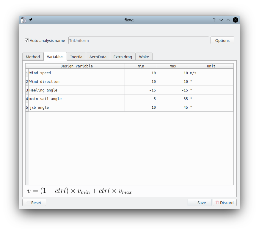
The analyses are intended to provide the forces and moments acting on the sails and the boat as a function of design parameters. The design parameters are:
- The wind's velocity (Apparent Wind Speed, AWS)
- The headwind angle (Apparent Wind Angle, AWA)
- The boat's heeling angle
- Each of the sails angle w.r.t. the boat
Back to top
Scripting
Scripting is done using xml files to define both the sails and the analyses to run. It operates in a similar way to the scripts for plane analyses.
An example of a script file is available here: boat_script.xml.
Back to top