Moments
Updated December 2, 2023
------------------ WORK IN PROGRESS ------------------
Context
Axes
The system of axes used for the calculations and the output of results in flow5 has been updated and is defined here.
Reference lengths
By default, the analysis defines and uses the following reference dimensions:
- Area (S): the plane's main wing area, projected on the x-y plane
- Span (b): the plane's span length, projected on the x-y plane
- Chord (MAC): the plane's main wing Mean Aerodynamic Chord
flow5 uses the standard conventions for the normalization of moments:
- Roll: L = ½ ρ.V2 S b Cl
- Pitch: M = ½ ρ.V2 S MAC Cm
- Yaw: N = ½ ρ.V2 S b Cn
Origin of moments
Moments are calculated around the plane's CoG. The CoG is defined as part of the plane's inertial properties.
An alternative option is to set manually the position of the CoG in the definition of the analysis, in which case it overrides the plane's properties.
Lastly the position of the CoG can be set as a variable in the control polars, in which case it also overrides the plane's properties.
Method
The evaluation of moments is done by summation of the individual moments of pressure forces acting on mesh panels.
In the case of the VLM:
- pressure forces are deduced from the panel's vortex strength
- fuselage panels are ignored in the analysis and do not contribute to the moments
- pressure forces are evaluated using the gradient of doublet strengths between a panel and its neighbours
- fuselage panels if present are included in the analysis and by default contribute to the moments
In addition, this part of the analysis is inviscid so that the calculated pressure forces are not damped by viscosity and may reach locally high unrealistic values. This is typically the case in two areas:
- the junction of the wing panels to the fuselage panels
- the wing tips
Fuselage contribution
The presence of a fuselage can be the cause of two distinct problems caused by the simplifications inherent to panel methods:
- The velocity gradients and the pressures can reach high values locally where the wing trailing edges connects to the fuselage. This is a numerical artifact and is a consequence of the absence of viscosity in the analysis.
- The wake panels or vortex lines which are sheddded from the wings' trailing edge in straight lines may interact numerically with the fuselage panels; in a worst case they may even intersect the panels.
Velocity gradients
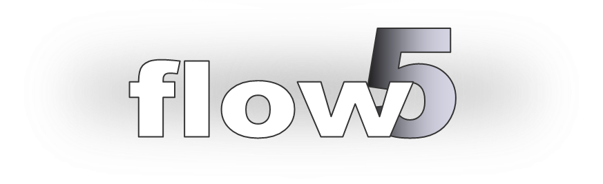
To see if this is a potential issue in the analysis, the simplest way is to display the panel forces in the 3d view. The pressure forces acting on the fuselage where it meets the wing's trailing edge are seen as radial arrows. Note however that these arrows only represent F/s = q.Cp and not the absolute panel force so that their effect may be less important than the display suggests.
These pressure forces are not likely to be concern in the case of longitudinal analyses with β=0°, since they are essentially lateral and do not affect the pitching moment to any great extent. It may be more of a problem in cases where β is non-zero.
Unfortunately there is no good way to avoid this problem.
Refining the fuselage mesh locally will reduce the area of the panels on which the high pressure acts, but it will also likely increase the pressures.
It is to be noted that due to numerical precision the left and right lateral pressure forces will not be stricly equal and therefore will not compensate each other.
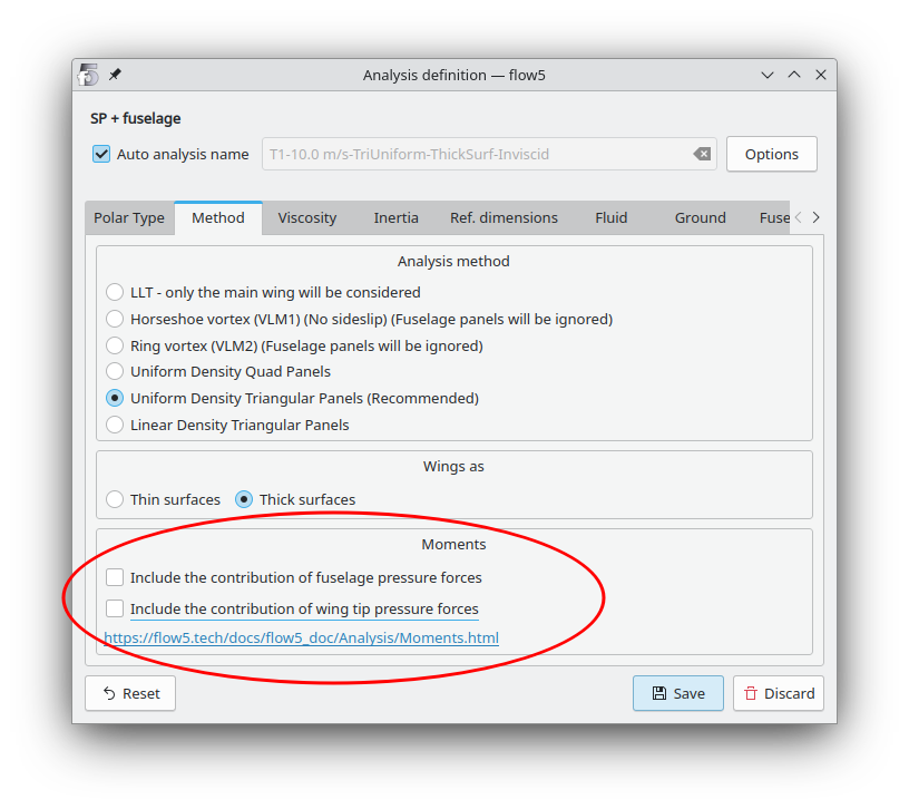
As explained below, there is an option in the definition of the analysis to ignore the contribution of fuselage pressure forces altogether, but since the fuselage's cotribution to moments is physically non negligible when sideslip is present, this may not be a solution at all.
Wake panel interactions
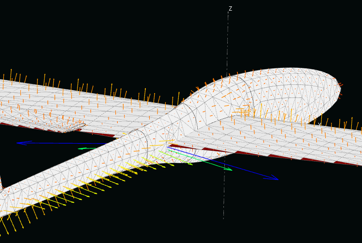
To see if this is a potential issue in the analysis, the simplest way is to display the pressure coefficients or the panel forces in the 3d view. The interaction of wake and fusealge panels manifests itself as perturbed pressure coefficients along the fuselage side.
The considerations mentioned above apply here also.
Note that the display in the 3d view of wake panels in the case of the linear analyses T123578 may be misleading since these wake panels are always aligned with the x-axis whatever the aoa, whereas they are displayed aligned with the wind direction.
Only in the case of T6 polars are the wake panels aligned with the wind direction for each operating point, which tends to improve the predictions of the analysis but also makes it non linear, i.e. the problem needs to be solved for each operating point.
The intended solution to this problem is the Vortex Particle Wake (VPW). The VPW will not completely eliminate the interactions since it still requires the insertion of a small set of wake panels at the wing's TE, but it will reduce them.
Another way to reduce the interactions is to increase the gap between wake and fuselage panels.
Back to top
Wing tip contribution
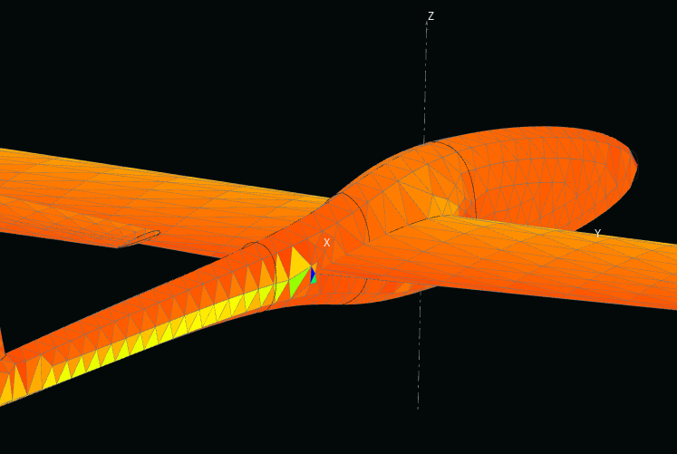
The issue of the pressure forces acting on the wing tips is similar to that of the fuselage interactions with the wing's T.E. and the same considerations apply.
It is possible to improve the evaluation of pressure forces at the wing tip by setting a number of strips greater than 1, and typically not more than three. This is defined in the wing geometry interface.
Testing so far has shown that it does not eliminate the problem since this area remains a location of high velocity gradients irrespective of the mesh density.
An option has been added in v7.24 to ignore altogether the contribution of wing tips in the evaluation of the moments.
Since there is no obvious downside to this solution, the recommendation is to activate the option and to exclude the wing tip panels in the evaluation of the moments.
Back to top