
Frames and axes
Updated June 15, 2026
------------------ WORK IN PROGRESS ------------------
Context
Several system of axes are commonly used in aerodynamic calculations, and the choice of the frame may depend on the method used or the type of results being calculated.
Typically, the geometry of the airplane is defined in a set of body axes called geometry axes in the case of flow5.
The lift, drag and side force coefficients are conventionally defined in wind axes, or pseudo wind axes ignoring sideslip.
Stability calculations are made in another set of body axes called stability axes.
AVL offers options to output results in either body or stability axes, with an option in each case to have the axes defined in the geometric or standard conventions, which makes for a total of four possible frames.
Up to v7.56 there have been some internal inconsistencies in flow5 in the sign conventions used for the output of forces and moments.
The purpose of this page is to clarify which frames flow5 uses in each case from v7.57 onwards.
Axes and frames of reference
Body axes
This term may refer to any system of axes which is fixed to the airplane and moves and rotates with it.
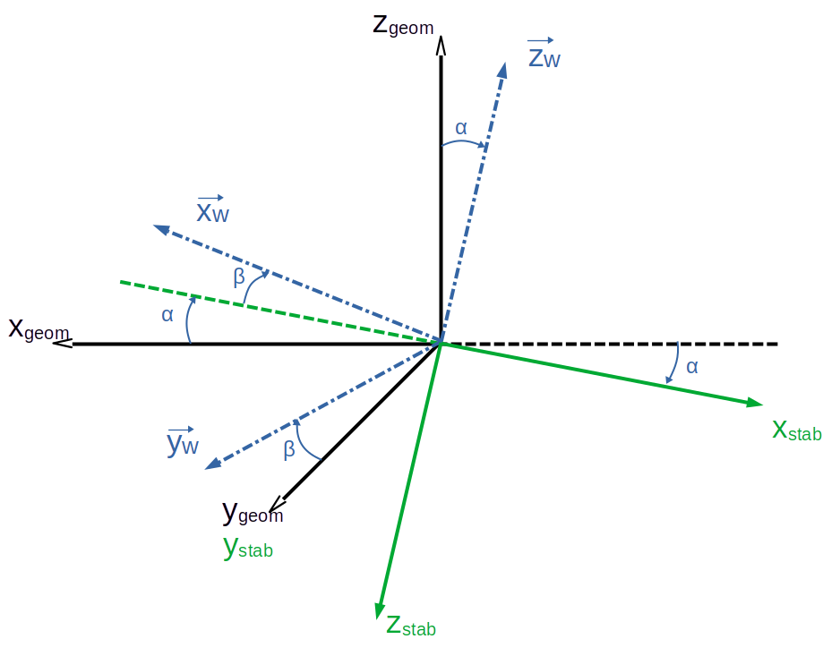
Geometry axes
In the case of flow5, this is the set of body axes in which the geometry is defined. It is also the set of axis in which the calculations are performed internally, even though the results may be output in a different set of axes.
- The x-axis lies in a horizontal plane and points backwards
- The z-axis lies in a vertical plane and points upwards
Wind axes
This is the frame of reference aligned with the wind.
- The x-axis and z-axis are rotated by the angle of attack from the geometry axes around the y-axis
- The z-axis is in the vertical plane and points upwards.
- The y-axis is rotated around the z-axis by the sideslip angle.
Stability axes
The stability axes are those defined in Etkin & Reid's "Dynamics of Flight" which is the theory implemented for the stability calculations in both xflr5 and flow5. A summary of the theory and a description of the frames are given in lecture notes 16 to 18 of this MIT course.
- The x-axis is aligned with the wind direction and points forward.
- The y-axis is the same as the y-axis of the geometry frame
- The z-axis is perpendicular to both and points downwards.
Choice of reference frame
Up to v7.56 and for consistency with AVL, flow5 used pseudo wind axes for the output of forces and moments, with the sideslip ignored.
Since v7.57, flow5 output of forces and moments in the "true" wind axes.Stability derivatives are output in stability axes.