
STL Planes
Updated October 11, 2020
STL models
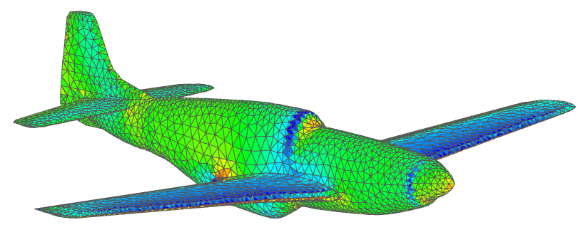
P51D Mustang Mk. III by M. Cel (http://hangar.openvsp.org/vspfiles/420)
meshed in OpenVSP and analyzed in flow5.
The STL standard
flow5 beta 14 introduces the option to carry out analyses on planes defined by imported stereolithography meshes. As the acronym suggests, STL models are essentially intended for the exchange of models for 3d printing. However, there is apparently no other universally accepted file format for surface meshes, so that the STL format has become the usual standard. The advantage of the format is that it is ubiquitous and versatile. It is therefore the format recognized by flow5 to import the surface meshes.
The only information contained in the STL file is the position of each triangle's vertices and its normal. It does not contain any meta data, or any information on mesh connections. All the additional information required to define a geometry and run an analysis needs therefore to be reconstructed in flow5, either automatically or manually as explained hereafter.
Mesh quality
Since flow5 is not intended to be CAD software, it does not offer any significant tool to correct, heal or improve the mesh. It is therefore important that the external STL mesh should be of a quality acceptable as-is for a panel analysis, i.e.:
- The union of triangles should define one or more closed non-intersecting volumes.
- All triangle normals should be pointing towards the outside of the volumes.
- The mesh should not contain any duplicate triangles.
- The mesh should not contain any null triangle, i.e. with a zero or a very small area.
- Adjacent triangles should be of comparable sizes; this is not strictly compulsory, but will contribute to improve the precision of the results.
- Triangles should be oriented positively, i.e. the vertices should be ordered in counter clock-wise order around the normal using the right hand rule; the program will automatically attempt to correct any triangle with wrong orientation.
Meta data
The information about the model which is not present in the STL file but which is required for the analysis is the reference wing area, the mean aero chord length and the span length. These dimensions are necessary for the calculation of the aerodynamic coefficients.
They should preferably be defined for the airplane, and if necessary adjusted for each analysis.
Element connections
The analysis requires that the mesh elements be connected, i.e. that each triangle "knows" with which other triangles it shares its edges, and that each node "knows" of which triangles it is a vertex. This information is not contained in the STL file and is reconstructed in flow5.
These connections are necessary to compute the pressure coefficients on the panels.
Trailing edges
The only other required information which is missing in the STL format is the location of the trailing edges and the identification of the triangular panels on the top and bottom sides of the trailing edges.
The definition of the trailing edges is required to implement the Kutta condition, without which the wake cannot be defined and the lift and induced drag cannot be calculated.
Back to top
Analyses
Viscosity
Since the STL format contains no information about the airfoils or about the fuselage, neither the viscous drag of the wings or of the fuselage can be estimated. The analysis will therefore only be of the inviscid type, although additional user-defined extra drag can be added to the results. An option to add AVL-type parabolic drag has been introduced in v7.01 beta 15.
Polar types
All the types available for flow5 planes are also available for STL type planes. However, without viscous information and viscous drag, type 3 "speed polars" will not be representative of the physical flight.
Fuselage interactions with wake panels
Since the fuselage is not identified in the STL file, the contribution of its pressure forces cannot be excluded from the calculation of the moments. This can be a problem in cases where the wake panels shed by the wings interact with the fuselage. To limit these issues, the use of a vortex particle wake is recommended.
Back to top
Step by step
A good starting point can be Tom's videos which show in detail the process to generate an STL mesh in OpenVSP and to import it into flow5:
- No. 1 - Exporting STL file from Open VSP: https://www.youtube.com/watch?v=ENXABhF-VkY&t=197s
- No. 2 - Importing STL files into flow5: https://www.youtube.com/watch?v=ENXABhF-VkY&t=197s
A project file containing examples of STL meshes can be downloaded here: STL_v7.22.fl5.
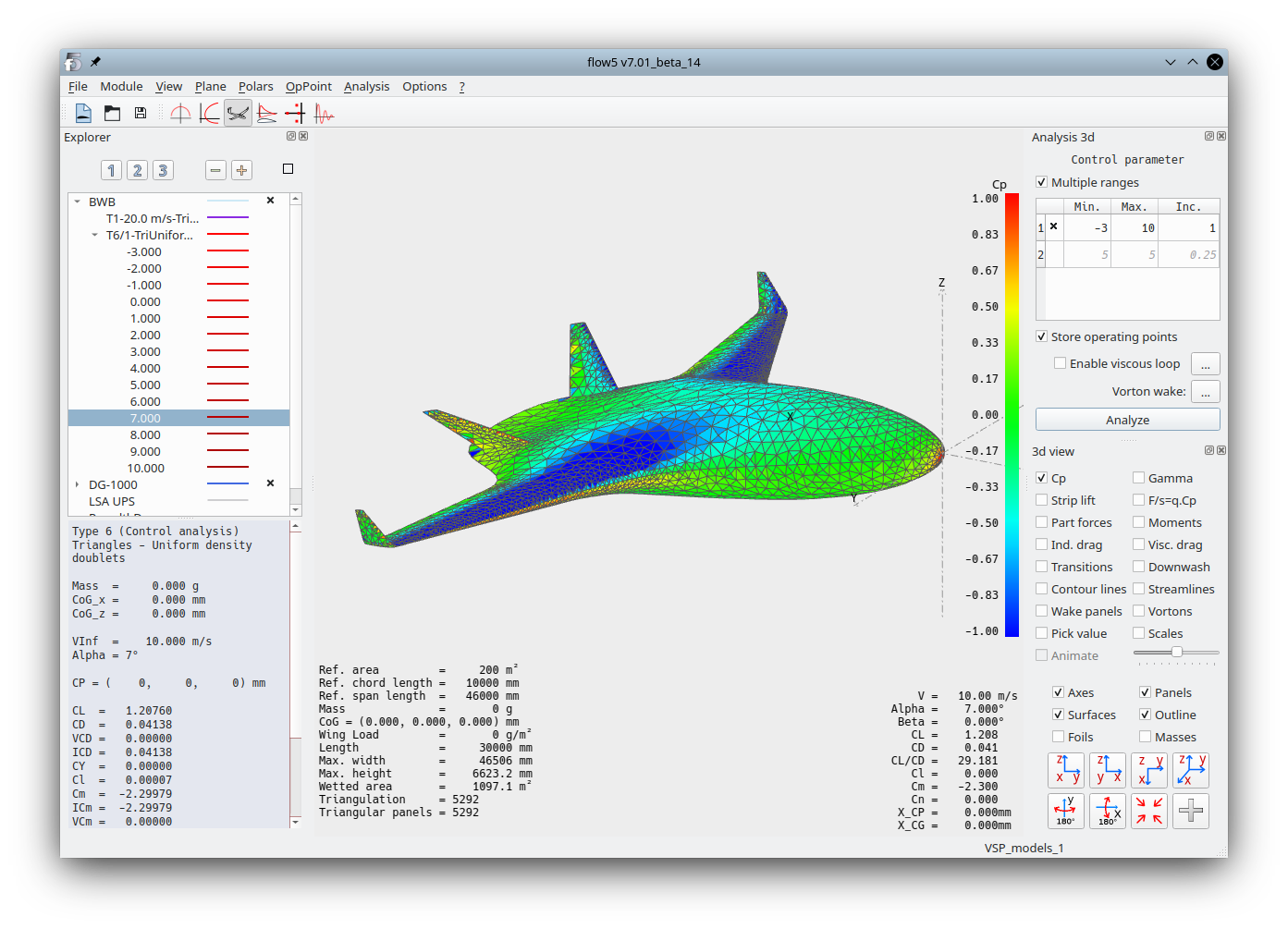
This step-by-step guide uses an STL model generated from the Blended Wing Body model built by Michael Kruger and which can be downloaded from the VSP hangar.
Import
Use the menu option Plane/Import/From an STL file to import a plane from an external mesh.
The length unit is not part of the STL format. If it is known, select the length unit with which the file was written, otherwise select a large unit, typically meters. The model may be scaled down at a later stage if necessary.
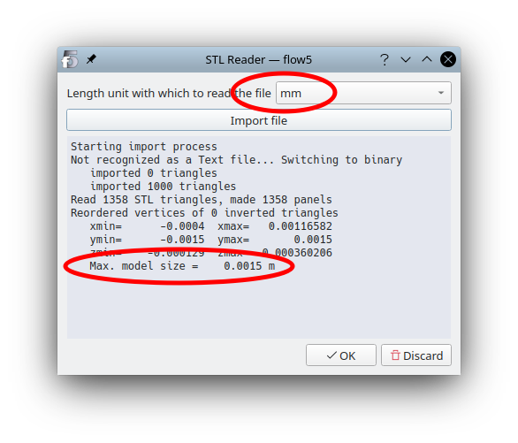
Reading for instance in millimeters a file written in meters will lead to a model of very small size. In the case illustrated in the image above, the size of the imported model is 1.5 mm. Triangles will have a very small area which could cause issues when scaling up the model. In such a case, it is recommended to restart the import process using meters.
The only check made during the import process is the verification and eventual correction of the triangles' orientation.
Editing
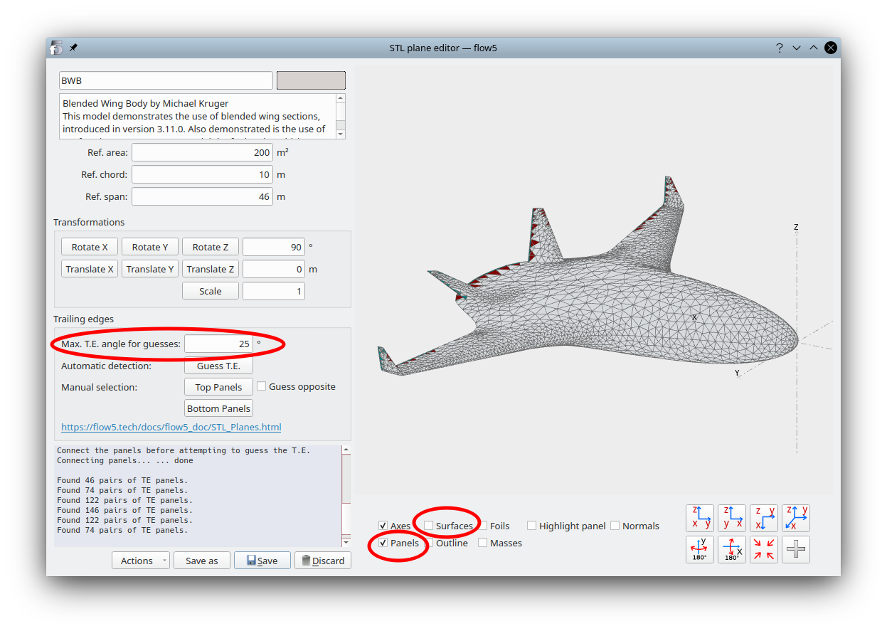
Once imported successfully, the program will show the plane editor, as illustrated below.
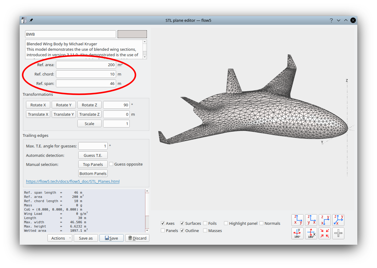
Meta data
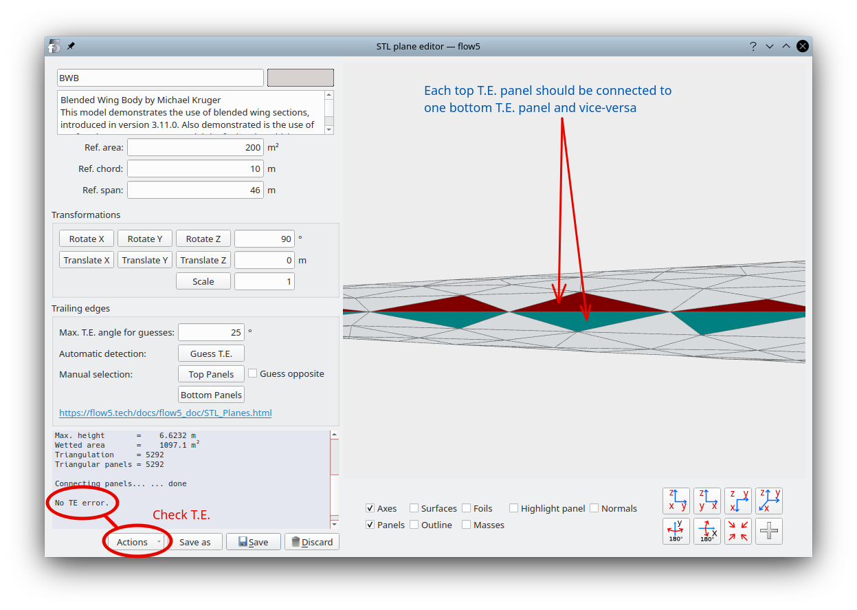
Use the interface inside the red circle to define the reference area, chord length and span length.
Trailing edges
The T.E. panels must be identified to meet the following constraints:
- The numbers of top and bottom trailing panels must be the same.
- Each top trailing panel must be connected to an opposite bottom trailing panel, and vice versa.
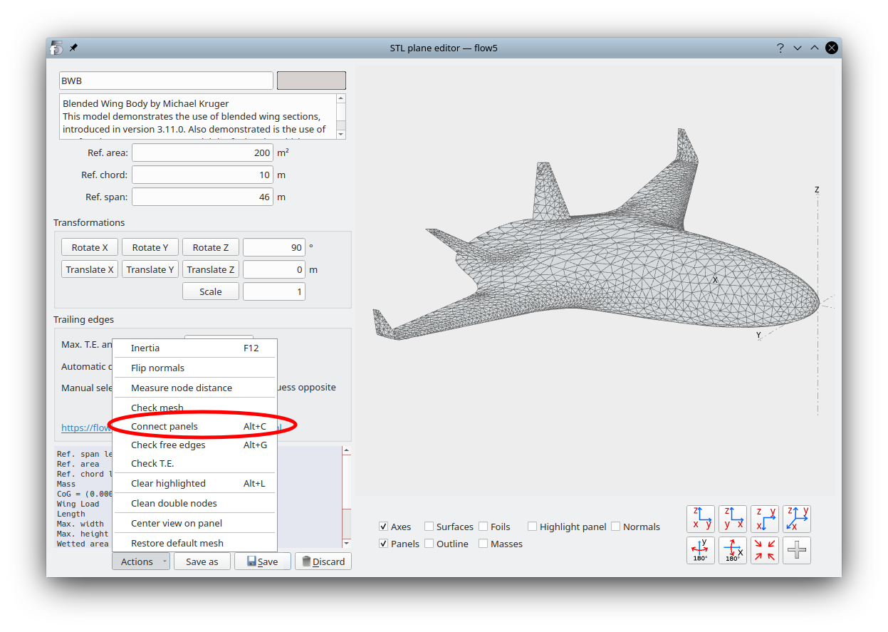
Element connections
To identify automatically the TE panels, the elements must first be connected.In the "Actions" menu, select "Connect panels".
You can take this opportunity to check the watertightness of the mesh by selecting "Check free edges". The free edges, if any, should be located at the trailing edges.
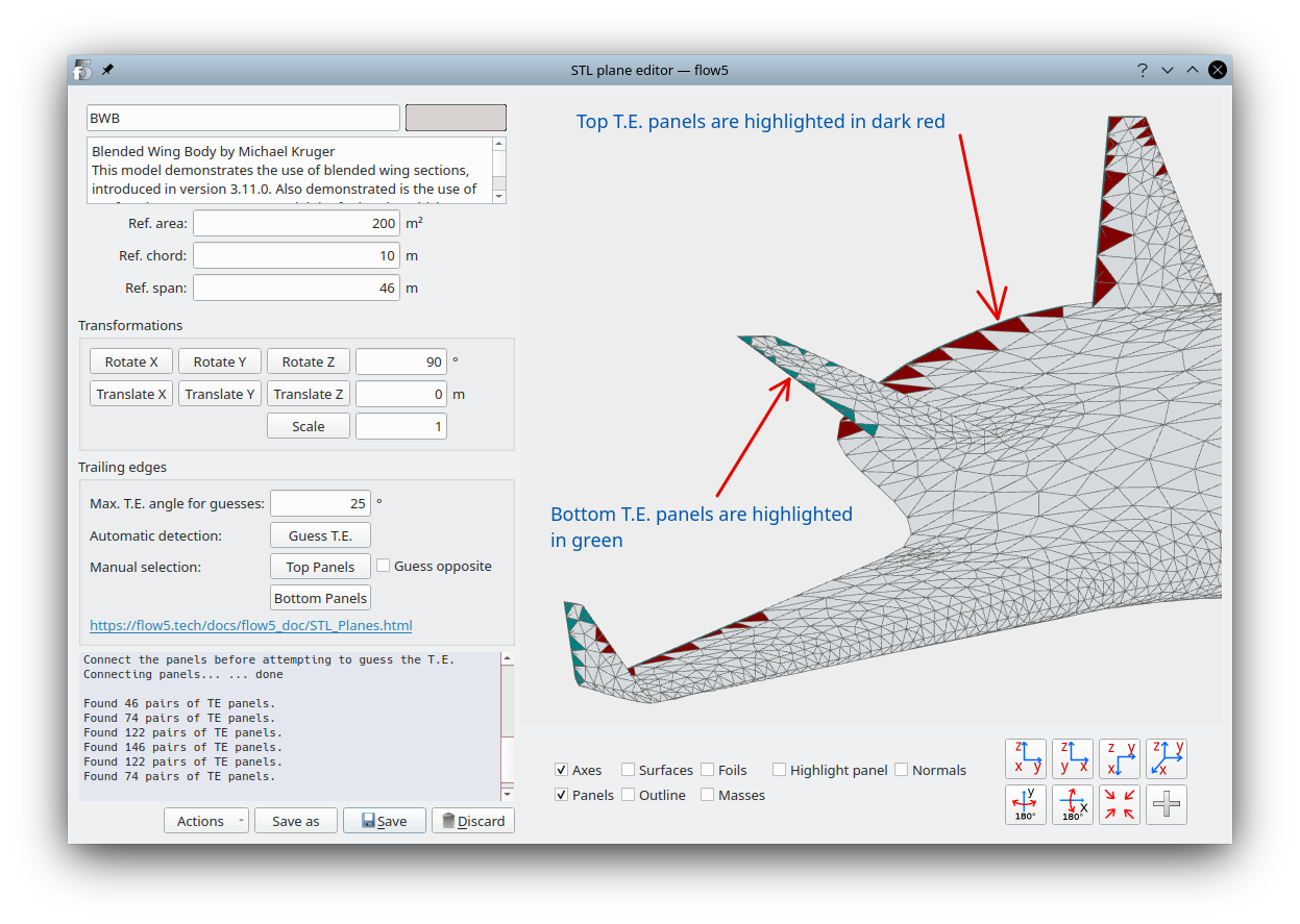
Automatic T.E. detection
flow5 will identify as T.E. panels any pair of connected triangular panels such that the angle between their opposite normals is less than the specified angle.
In the 3d view controls, de-select "Surfaces" and activate "Panels".
Specify a value for the T.E. angle. Start preferably with a small max. value such as 5 to 10°, and increase it progressively.
Click "Guess T.E.".
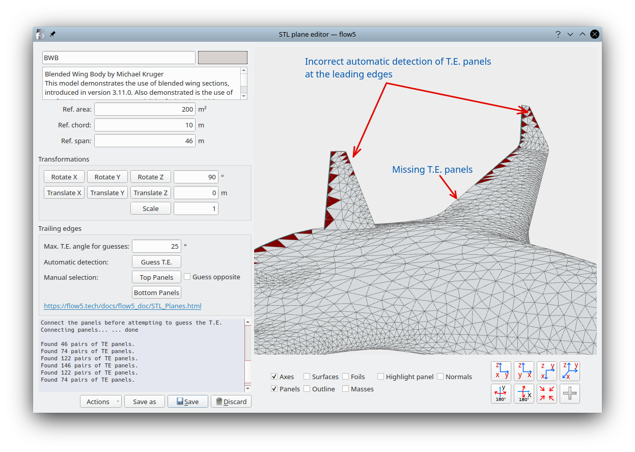
- if pairs of triangles other than at the T.E. have been selected
- if pairs of triangles are missing at the T.E.
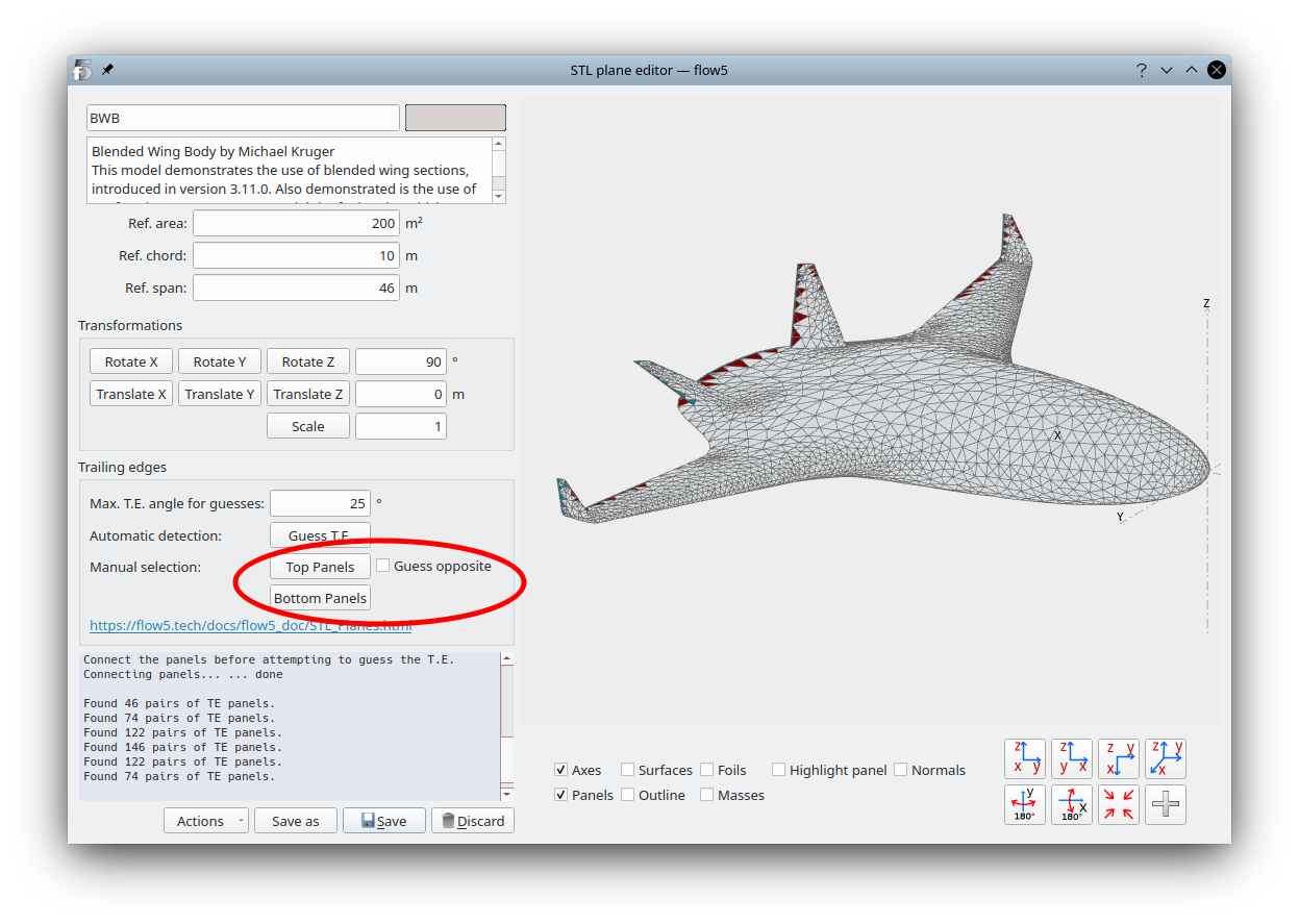
Manual T.E. selection and correction
The set of T.E. panels will likely require manual correction.
Click first on the button "Top T.E. panels" to activate their selection. Then click on the panels in the 3d view to select or deselect them one by one.
If "Guess opposite" is selected flow5 will attempt to identify the T.E. panel on the bottom side for each selection, using the max. specified T.E. angle.
Make sure that each top T.E. panel is connected to one bottom T.E. panel and vice versa.
In the "Actions" menu select "Check T.E.". The message "No T.E. error" should show up in the output window. If this is not the case, manual correction of the highlighted panels is required.
Note that this check process will not identify as incorrect selections of T.E. panels located elsewhere than at the trailing edge, since the application has no way to do it.
Common errors
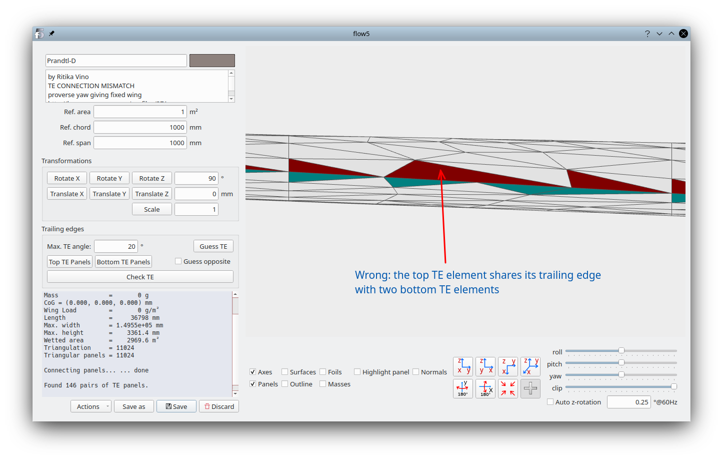
Other than the incorrect detection of T.E. panels at locations other than the T.E., the two potential errors are mismatches of T.E. panels and holes in the mesh.TE element mismatch
It may occur that the T.E. elements on the top and bottom surface do not match, in which case flow5 will be unable to connect the panels as illustrated below. This is the case of the "Prandtl-D" wing mesh in the demo project file. This mesh was created by the OpenVSP surface mesher and imported into flow5.The analysis will not run if a mismatch is detected.
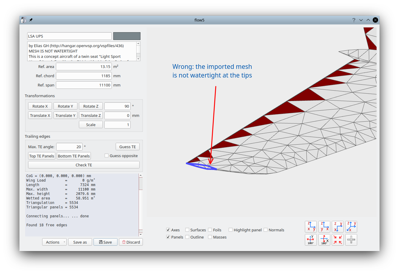
Mesh is not watertight
flow5 will find free edges at locations other than the T.E. if the mesh is not watertight. This is the case of the "LSP UPS" mesh in the demo project file. This mesh was created by the OpenVSP surface mesher and imported into flow5.Note that the analysis will run nonetheless, but the results will not be valid.
Final checks
- Click on the button "Check T.E." and make sure that the message "No T.E. error" is displayed in the bottom left output window. Otherwise, correct the selections of the top and bottom trailing edge panels. Faulty panels will be highlighted in blue in the 3d view.
- In the bottom left "Actions" menu, select "Connect panels". Wait until the message "Connecting panels... done" is displayed in the bottom left output window.
- In the "Actions" menu, activate "Check free edges". The program should only find free edges at the trailing edges, or none at all depending on how the STL mesh was constructed.
Next steps
- Define the inertia using the menu option in the "Actions" button, or with the F12 shortcut.
- Save the plane and continue to define and run an analysis as for an internal flow5 model.
Back to top