Fuselage from CAD files
Updated September 24, 2020
------------------ WORK IN PROGRESS ------------------
CAD type fuselage
CAD files
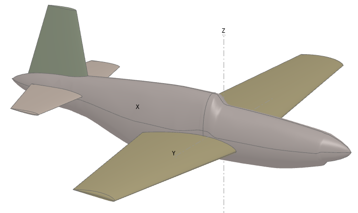
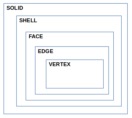
Once imported, the models are stored and handled as OCC objects. A model is structured in a topological hierachy going from SOLID to VERTEX objects.
A CAD file should include at least a set of FACES which defines one closed volume.
Internally, flow5 uses the SHELL to represent a fuselage's shape. A SHELL is a union of connected FACEs.
SHELL structures however are not required to be present in the STEP file since they can be reconstructed in flow5.
flow5 uses the sub-structure of FACEs to build the connections between the wings and the fuselage. It is important that this set of FACEs is as simplified as possible to facilitate meshing operations, e.g.:
- They are not delimited by small edges, otherwise the mesher will either fail or will attempt to build a great amount of surface elements to adapt to the edge's length.
- The set should define a closed volume, even if the corresponding SOLID and SHELL structures are not present in the CAD file.
This means that there shouldn't be any gaps between the FACEs.
Fuselage as a plane part
The BEM requires that the plane and wings be merged in one or more closed non-intersecting volumes.
To achieve this, the fuselage needs to be hollowed out were they connect. This is achieved using OCC's boolean operators.
The detailed process to assemble the plane is described here [link].
Only the uncut shapes are stored in the project file. The cut geometries are meant to be meshed immediately after the boolean operation and are discarded when the project is unloaded.
Step-by-step
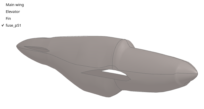
A project file with examples of fuselages imported from STEP files generated by OpenVSP can be downloaded here: STEP_fuse.fl5
STEP file creation
The fuselage model used for this tutorial is the one from the P51D Mustang project (http://hangar.openvsp.org/vspfiles/420). The fuselage has been exported as a STEP file using VSP's default settings.
STEP import into flow5
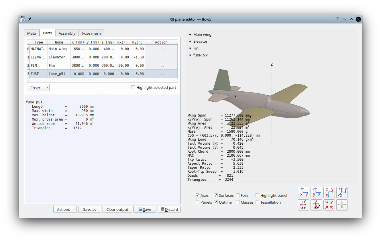
Fuselage objects are imported using the Insert menu in the plane editor.
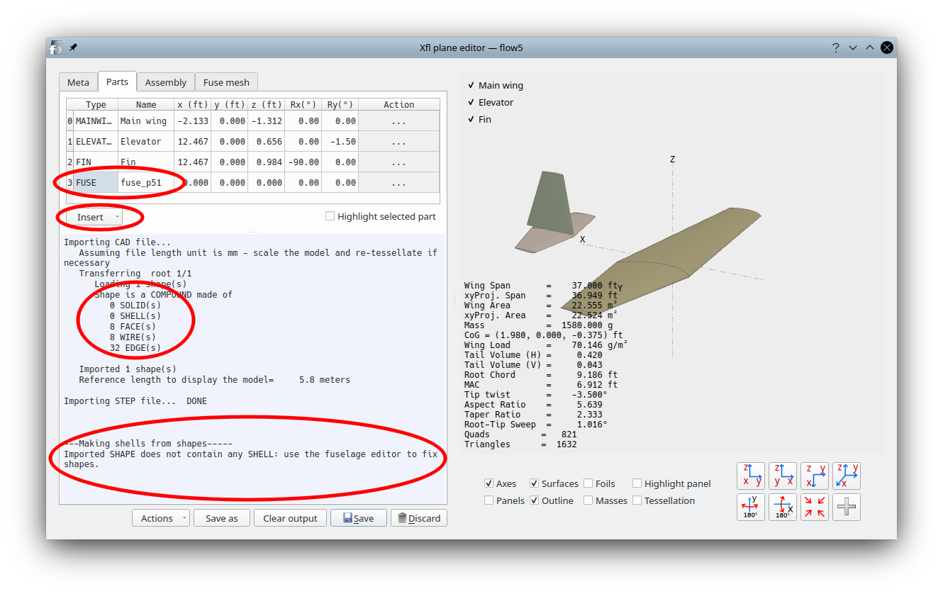
To create the SHELL and eventually fix the topological shapes, open the fuselage editor by clicking on the three dots in the right "Action" column.
The fuselage will not appear in the 3d views until the SHELL(s) have been built.
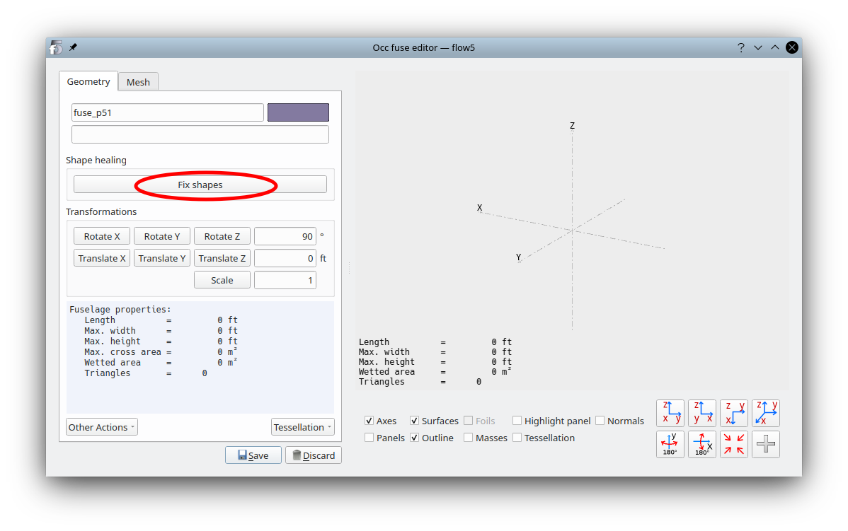
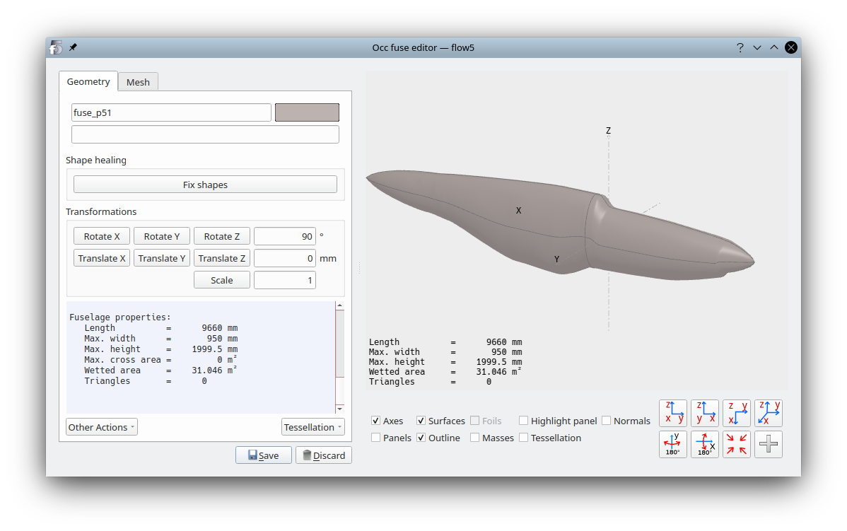
In the editor, click on the button "Fix shapes" to open the shape fixer interface.
Face stitching
Click on the "Stitch shapes" button. This will launch the sewing of FACEs.
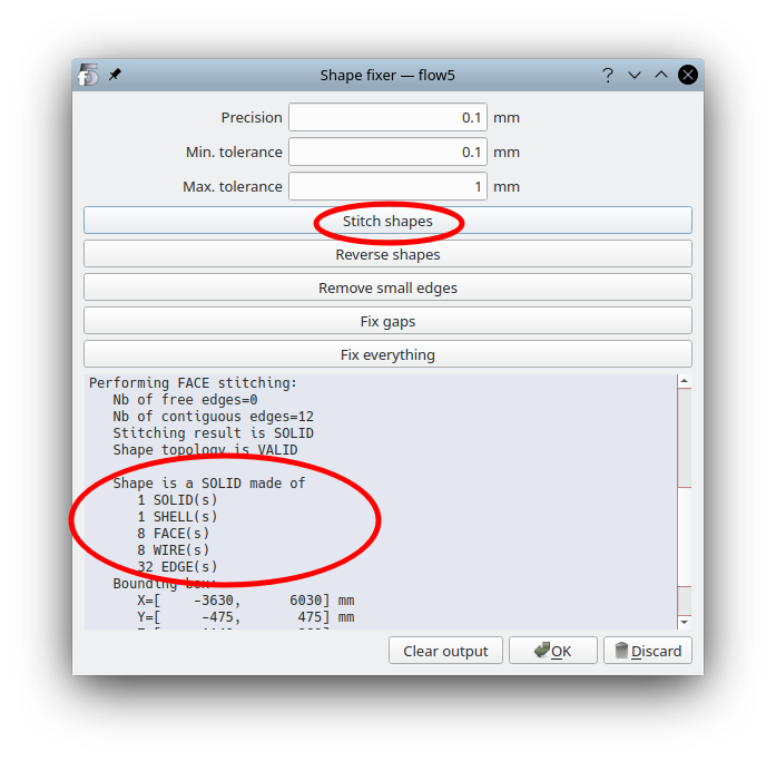
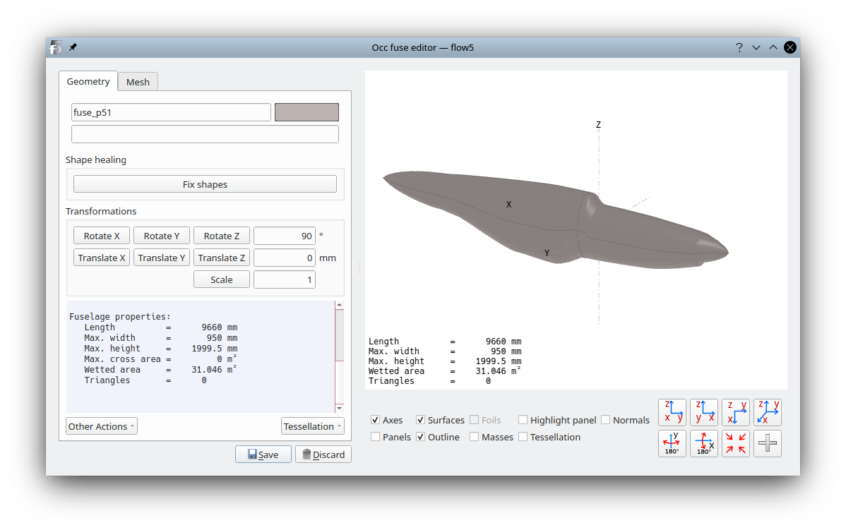
Click OK to save the change and exit the interface. The fuselage should now appear in the 3d view.
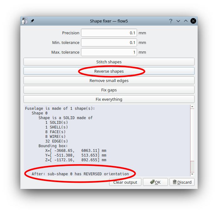
Shell orientation
Open again the shape fixer interface, and click this time on the button "Reverse shapes". The output shows that the topological orientation has been reversed, meaning in this case that the normal is now pointing outwards.
Click "OK" to save the change.
Sanity checks
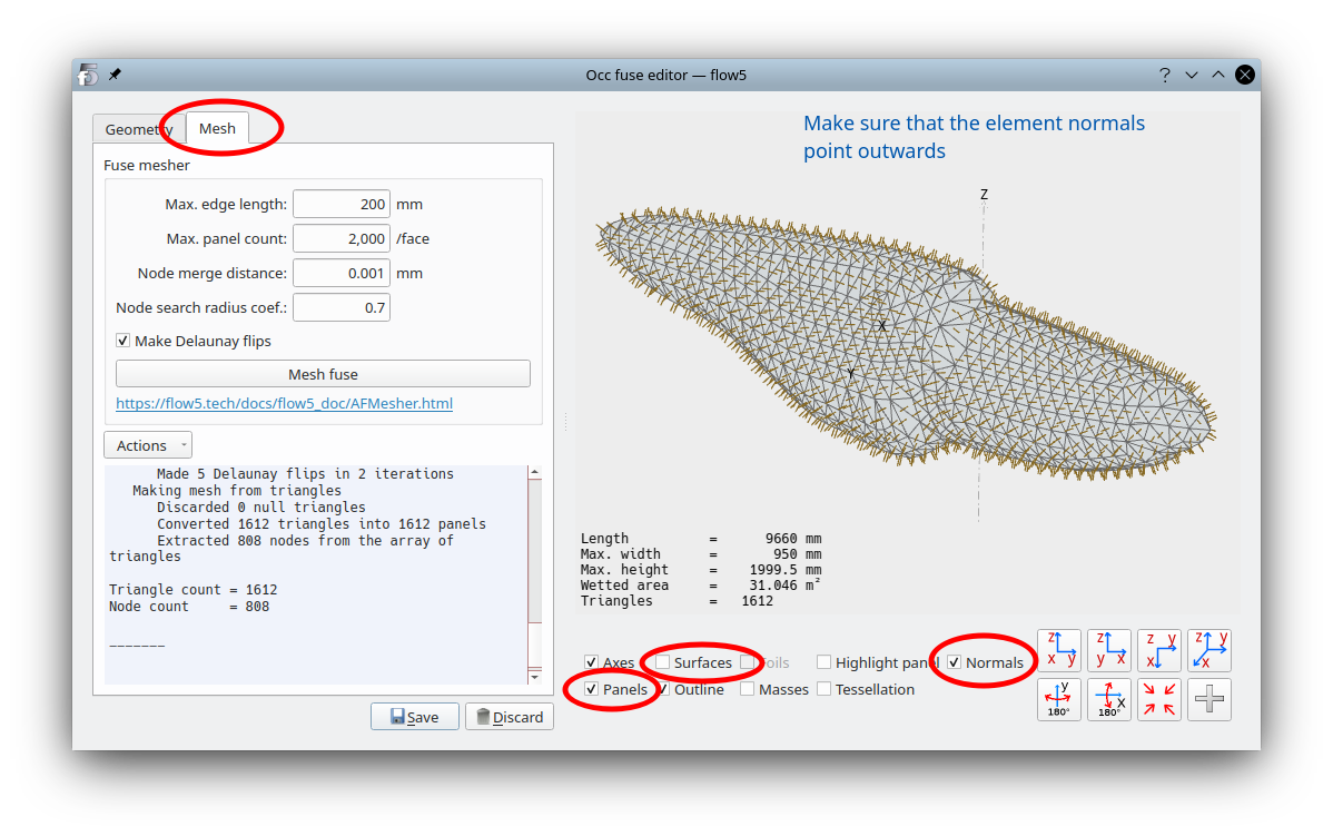
To verify the soundness of the model, a first mesh can be generated. This mesh will be overwritten after the plane is assembled.Move to the "Mesh" tab, select parameters suited to the plane's geometry and launch the mesh operation.
If the mesh operation fails, see the detailed explanations here.
The things to check are:
- the orientations of the element normals towards the outside of the volume
- the absence of free edges which would indicate the presence of holes
To verify the orientations of the surface elements, display the "Normals" in the 3d view and make sure that they point outwards.
--- For versions >= v7.01 beta 16 only -----
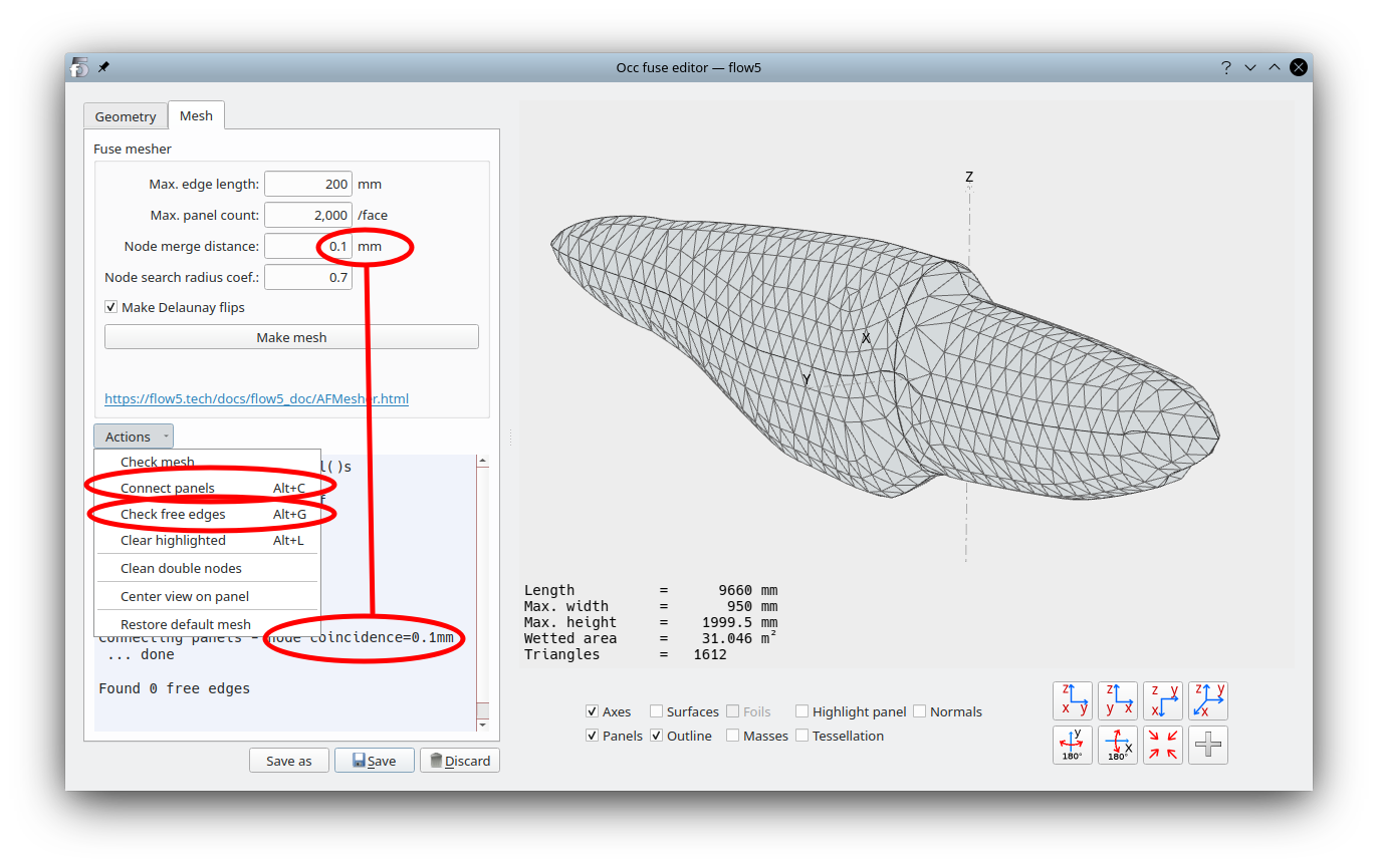
If a SOLID has been successfully built, then it is likely that there are no gaps in the topology. As an extra precaution, it is possible to verify the absence of free edges in the mesh.
Make sure that the node coincidence distance is suited to the element size. Typically this distance should be 0.1 mm. Triangle vertices closer than this length will be considered identical.
Connect the elements using the option in the "Actions" menu. This is a necessary step since a free edge is identified as an edge belonging to only one triangle.
Finally, request a "Check free edges". None should be found.
Back to top