Connecting the fuselage and wing meshes
Updated April 16, 2026------------------ WORK IN PROGRESS ------------------
Context
In order to produce valid and accurate results, the assembly of the fuselage and wing meshes must follow rules which differ in the thin and thick surface cases.
In the thin surface case,
- the meshes of the parts must not be intersecting;
- the meshes must be connected at the element nodes.
In the thick surface case,
- it is necessary for the union of meshes to define one or more closed and non-intersecting volumes;
- ideally, the fuselage and wing meshes should be connected at the element nodes, however this requirement is not mandatory
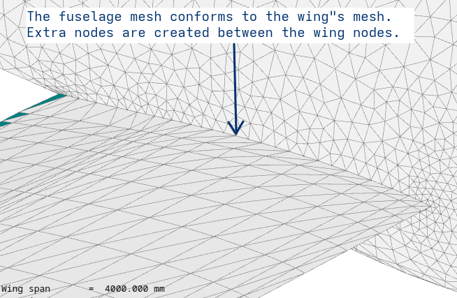
Fuselage and wing meshes connected at their nodes are referred to as "conforming meshes".
Although any number of fuselages can be included in the plane model, flow5 only handles the assembly of the first one in the list. In addition, flow5 assumes that this fuselage is positioned in the vertical plane defined by y=0.
The simplest and recommended method is the thin surface assembly.
Note that whichever assembly method is selected, the same type of method will need to be selected manually when defining analyses at the next stage.
Back to top
Gmsh
Internally, flow5 uses the open-source mesher Gmsh to build the conforming fuselage mesh.
Numerical experiments so far seem to show that Gmsh always succeeds in the case of the native xfl-type fuselages, i.e. NURBS and QUAD types.
It fails occasionally in cases of imported STEP fuselages, apparently due to small edges or faces. These small entities may be present in the imported geometry, or may be created when the fuselage and wing surfaces are assembled.
In such cases the problem can usually be fixed by
- "Cleaning" the fuselage in the CAD application before exporting it to STEP; the cleaning operation consists in removing small edges and faces even if at the cost of an alteration of the exact geometry;
- in flow5, by moving the parts relative to each other to avoid intersections which create small entities on the fuselage
Gmsh may add automatically intermediate nodes on the fuselage between the wing nodes. This has no consequence on the results.
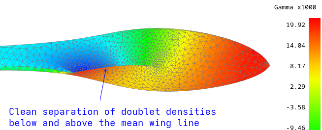
Thin surfaces
The goal is to ensure that no fuselage element extends both below and above the wing. This ensures that the calculated doublet distributions on the fuselage elements below and above the wing at the wing roots are cleanly separated as illustrated in the image on the right.
For information, this clean separation can not be achieved in xflr5, and is the reason why the thick panel method is disabled in the legacy app whenever the fuselage is included.
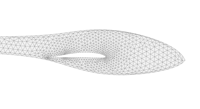
Thick surfaces
The goal is to remove all fuselage elements located inside the wings to achieve the mesh illustrated in the right side image.
This ensures that the assembly of meshes creates one closed volume with no internal elements inside.
Step by step
The method to assemble the meshes is the same in both the thin and thick surfaces cases.
Open the plane editor.
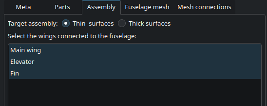
In the "Assembly" tab:
- Select the type of assembly: thin or thick surfaces
- Select the wings which are to be connected to the fuselage
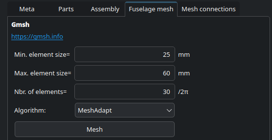
In the "Fuselage mesh" tab,
- Define the mesh parameters
- Request the construction of the mesh