
Thick solid sails: the windsurf example
Updated January 16, 2021
------------------ WORK IN PROGRESS ------------------
Context
The simplest way to analyze a windsurf sail is to model it with thin mesh panels associated to the Neumann Boundary Condition (BC).
At the next level however, it may be desirable to include in the model the mast and the thick sleeve which contains the mast. This thick part of the model is associated in flow5 to Dirichlet BC. Although the mix of thin and thick models BC poses no special theoretical difficulty, it leads to significant increase in the code complexity and the UI, with limited benefit in terms of analysis accuracy. It is therefore not an option as of flow5 v7.03.
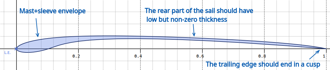
After some exploratory testing, the recommendation in such a case is to represent the sail as a thick volume with low but non-zero thickness in the rear part of the sail.
A simplified example of a windsurf sail can be downloaded here: windsurf.fl5.
Back to top
Geometry
The intent in flow5 is that the sail is defined using design parameters to enable and facilitate sensivity analyses and optimization.
The main design parameters are:
- the sail sections,
- the rotation angles of the sail in 3d space,
- the airfoils and their position in the sail's frame of reference.
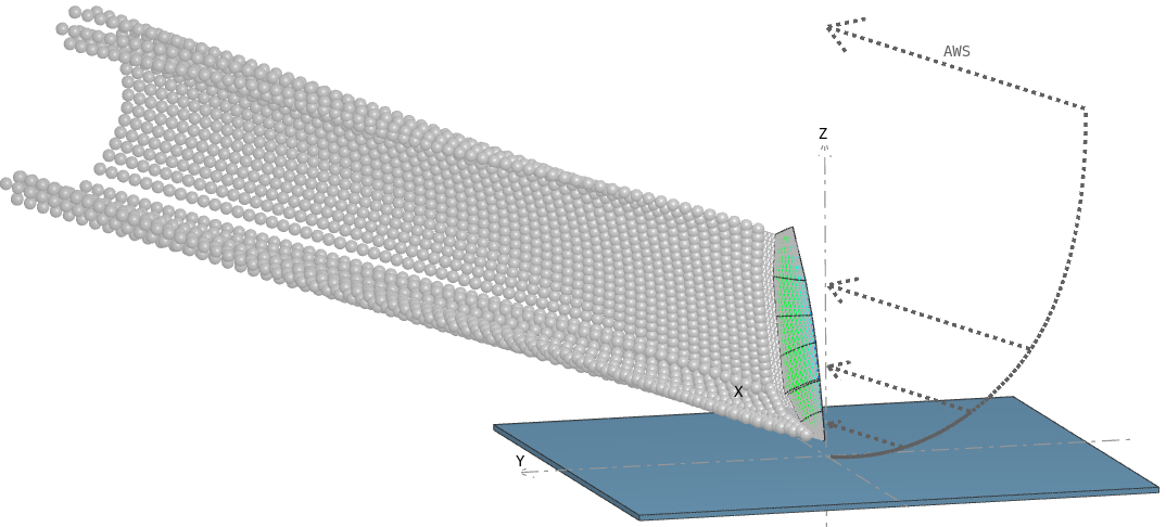
The sail should be built in a reference frame such that the mast is contained in the xz plane and the y-axis is oriented towards starboard. The sail can be rotated in any position by setting the appropriate angles in the definition of the sail analysis.
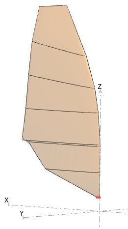
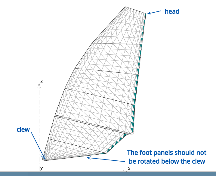
In the case of a thick solid sail, the clew and head corner points are determined automatically by flow5, and the trailing edge is constructed between these two points. It is important that the sail should not be rotated around the y-axis by an angle such that the sail's foot edge is lower than the clew, which would cause unwanted numerical interactions between the sail's panel and the wake panels.
An option to set the corner points manually may be added in a future version.
Back to top
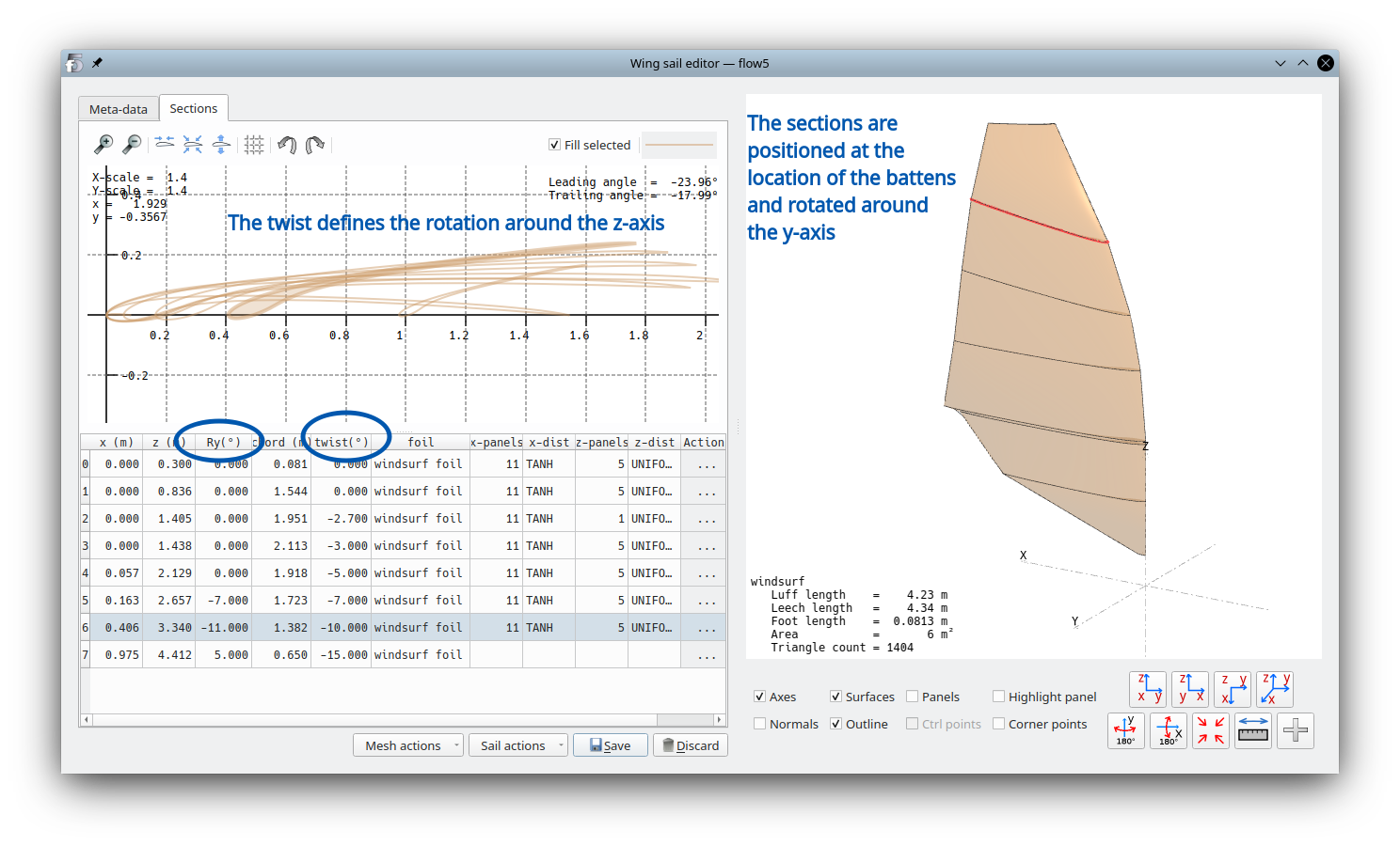
Airfoils and sail sections
Airfoils are constructed for each section. The rear part of the foil should have minimal but positive thickness to avoid numerical interactions between the leeward and windward sides of the sail. Typically a thickness of ~5mm ensures that this condition is met.
The intent is that the sail's airfoils should be defined in the direction of the battens, and rotated in position around the y and z axes using the fields "Ry" and "twist".
Back to top
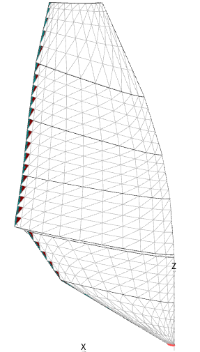
Mesh
Due to the structured nature of the geometry, only the ruled mesh option is available.
The density of the panels should be increased at locations of high pressure gradients, which in this case are the sail's edges.
Back to top
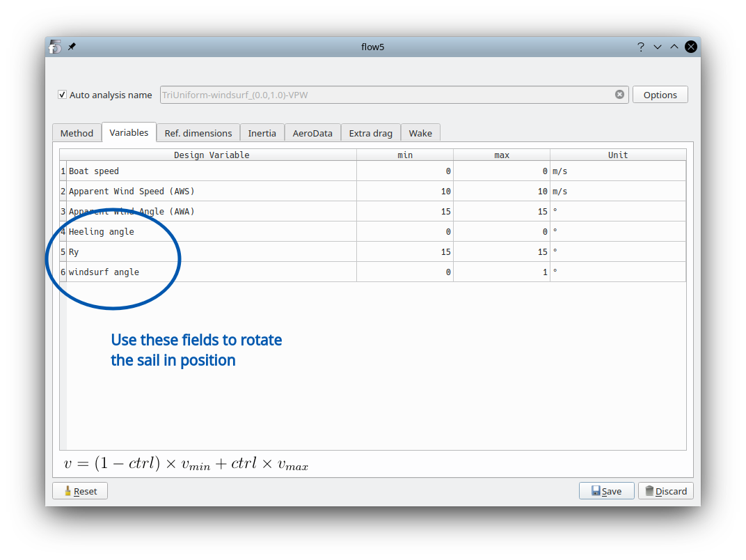
Analysis
As is the case with planes, wings and all other models available in flow5, the recommended analysis method is the triangle uniform type for its simplicity, robustness and versatility. Numerical experiments have shown that the linear model does not improve the accuracy significantly, but increases the analysis times by a considerable factor.
Although there is no risk in the case of a windsurf of interactions of wake panels shed by an upstream sail, the recommendation is to use the Vortex Particle Wake model for its better accuracy compared to the flat wake model.
The sail can be rotated in position using the heeling, Ry, and sail angles.
Back to top