
flow5 v7.01 beta 09 release information
Updated June 13th, 2020
Induced drag
The evaluation of the induced drag in the far-field Trefftz plane can be a bit tricky in the case of panel methods.
As a reminder, in the case of the VLM the trailing vortices are concentrated at the edges of the wing's strips, and they extend to infinity.The induced velocity and drag can therefore be evaluated downstream in the middle of the strips without any numerical difficulty.
In the case of a panel method, the wake is modelled as flat panels of finite length, and the induced velocity is evaluated on the panel itself. This creates numerical difficulties due to the singular behaviour at the panel edges.
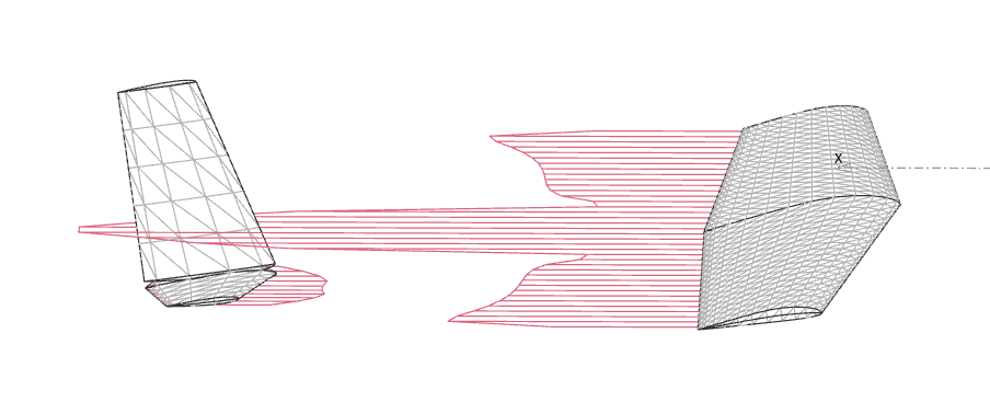
Up to beta 08, the induced velocity was evaluated at the trailing point of the wake panels, as illustrated below.

An unfortunate consequence is that the trailing edge of the last wake panel could cause apparent negative drag on the elevator. This effect is purely numerical.
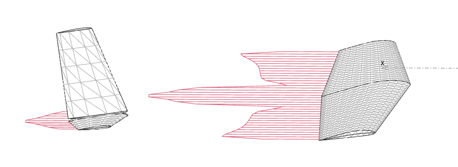
To avoid this end effect, the induced velocity is evaluated in beta 09 half-way down the wake panels.

This solves the issue of apparent negative drag. The estimation of the overall drag does not change significantly.
The main recommendation for all versions is to define a wake sufficiently long so that the effect of the plane's surface panels is not felt. Typically the wake's length should be greater than 30 MAC. The number of panels down the wake is parametrizable, but seems to make little or no difference to the results.
The recommendation is therefore: wake length length = 30 MAC or greater, 5 panels downstream, and a progression factor = 1.1.
Back to top