
Foil and plane trailing edge flaps
Updated January 11, 2026------------------ WORK IN PROGRESS ------------------
Context
The handling of trailing edge flaps has been modified in v7.50 compared to the method used in xflr5 and previous versions of flow5.
The purpose of this page is
- to provide background explanation of the changes,
- to provide a quick guide to the use of the new features.
Video explanations are available in the "flow5 practices" playlist on YouTube.
Description
In xflr5 and in flow5 up to v7.25, T.E flap angles are a property of the foil and plane objects. As a consequence each set of T.E. flap angles requires the definition of a specific foil or plane geometry. In turn this requires that a foil and its viscous data be built for each flap angle.
Since flaps operate more often with non-zero deflection angles than not, the goal is to make the calculation of flapped configurations quicker and simpler, and to remove the need to build a specific object for each.
Starting in v7.50:
- The hinge location remains a property of the foil.
- The flap angles become a property of the foil and plane analyses.
- The management of the leading edge flap is unchanged from the legacy versions and remains a property of the objects.
The change comes with some drawbacks:
- Former existing plane polars of flapped configurations are no longer usable; they are still visible in the polar graphs but will need to be duplicated and recalculated.
- Since the influence matrix in 3d depends on the flap configuration and therefore on the active polar, the option which authorized the storage of unit solutions and their re-use across T123578 polars is no longer possible and has been removed.
Notes:
- Unflapped foils and planes can be used and analyzed as in former versions of flow5.
- It is still possible to make a foil's T.E. flap angle permanent. When this option is selected, the foil is modified to include the deflection and can be used as in former versions fo flow5.
However, the setting of a permanent non-zero T.E. flap angle should be seen as a back-up option. The design intent and the preferred option is to use the flap angle as a variable in the analyses.
Examples
Examples of flap constructions: Flaps_v750.fl5
Foils
Foil initialization
Once loaded, a foil should be initialized with the following operations:
- smooth repanelling with ~150 panels, including higher panel densities at the L.E. and T.E.
- if the foil is to be used with a T.E. flap, the hinge location should be set before any calculation.
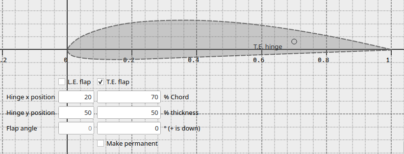
The T.E. hinge location is set as in former versions using the flap management interface (F10).
A value of T.E. flap angle can be entered in this interface. The goal is to allow testing of min. and max. values of the angle to check that the geometry remains smooth and usable within those limits. The deflection will be discarded when exiting the editor, unless the option "Make deflection permanent" is activated.
If the option "Make deflection permanent" is activated, the foil's geometry is modified to include the deflection and can be used as in former versions of flow5. This however is not the recommended option. Instead, the intent is for the flap angles to be set at the next step when the analysis is defined.
Important: To be consistent with the limitations of the panel methods and of implicit laminar flow, the min. and max. flap angles should remain small.
Foil analysis
Analysis definition
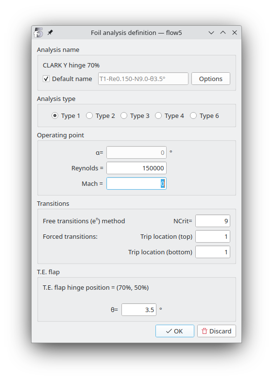
The T.E. flap angle is denoted θ and is defined in the bottom box of the form.
The other parameters are unchanged.
Type 1-2-3
The T.E. flap angle is a fixed parameter of the analysis.
The Reynolds number is a fixed parameter of the analysis.
The analysis variable is the angle of attack α.
Type 4
The angle of attack α is a fixed parameter of the analysis.
The T.E. flap angle θ is a fixed parameter of the analysis.
The analysis variable is the Reynolds number.
Type 6
The angle of attack α and the Reynolds number are fixed parameters of the analysis.
The analysis variable is the T.E. flap angle θ.
Planes
Procedure
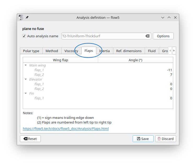
The way to proceed in v7.50 is to define the plane with all T.E. flap angles set to zero, and to define one analysis for each set of flap angles.
As a consequence, if the plane was defined in a legacy version of flow5 with non-zero T.E. flap angles, the associated polars are no longer compatible with the updated plane geometry.
When the analysis is run, the mesh is modified by rotating the flap surfaces around their hinge vector. This implies that the influence matrix and the RHS are built and the linear system is solved for each analysis run. The former option to store the linear solution and use it across all linear analyses is no longer available.
When the flap deflection is non-zero, the viscous drag should not be interpolated on the 2d polar mesh which is not applicable.
Instead the viscous drag should be evaluated "on the fly". This is done by selecting the option in the plane polar editor.
The method to conduct a sensitivity analysis with varying flap angles is to use T6 polars. This is unchanged from legacy versions of flow5.
Flap models
The recommended procedure to define flapped wings in xflr5 and legacy versions of flow5 has been to duplicate wing sections at each end of the flaps. This is no longer required with the new method.
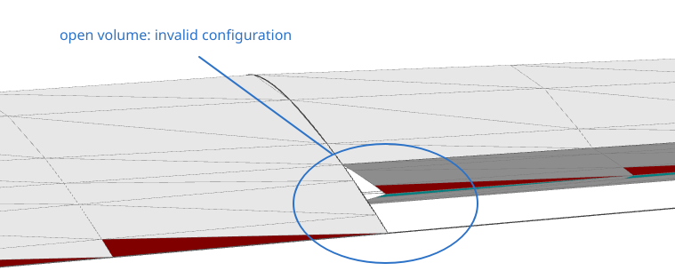
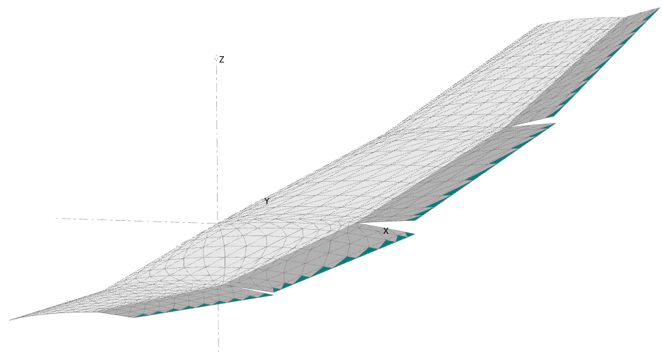
Thick surface analyses
In the case of thick surface methods, the deflection of flaps has the inconvenience of leaving volumes opened at the extremities.
A model with an open volume is theoretically invalid in a boundary element method, and leads to a numerical error.
Numerical tests seem to show that this error is negligible in most cases.
Thin surface analyses
The recommendation is to use the thin surface model whenever flaps are deflected.
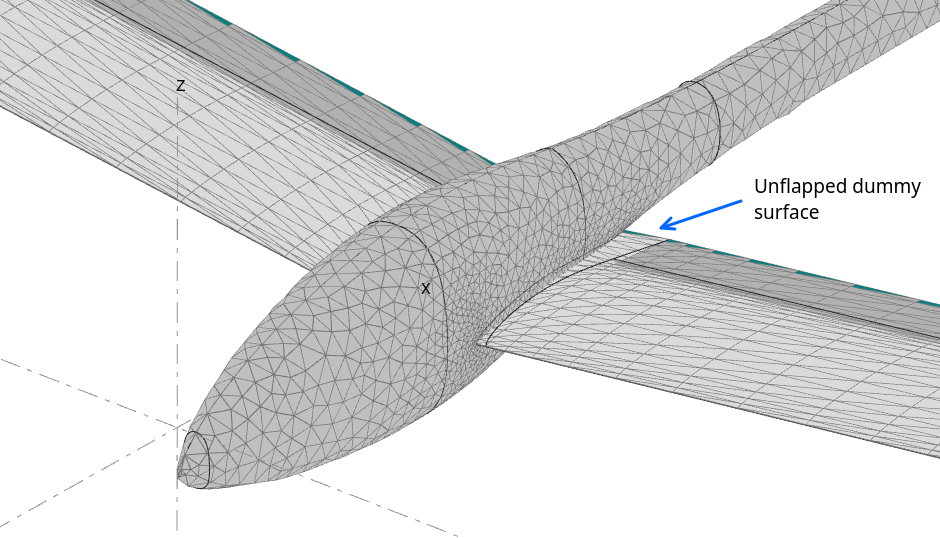
Flaps and fuselages
If a fuselage is included in the model, special care should be given to the connection of the wing and fuselage meshes.
The recommendation is to:
- use the thin surface model
- insert an un-flapped, i.e. dummy surface at the root of the wing;
- connect the wing to fuselage using the conforming mesh option
Flap intersections
Special care should be taken to avoid panel intersections when setting flap angles. These may typically arise in adjacent wing panels with non-identical dihedral angles as illustrated in the image on the right.
Intersections, or parasite numerical interactions may also arise if the flap is adjacent to a fuselage.
Since flow5 cannot detect these intersections, the analyses will run but will yield spurious results.
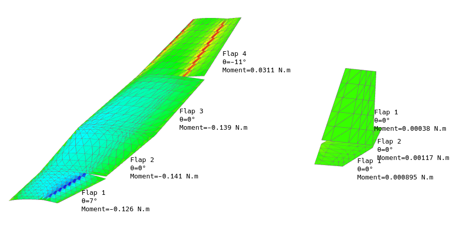
Such interferences can often be detected by displaying the doublet densities in the 3d view. They will show up as anomalies on the color map.

Legacy models
When projects including flapped configurations are imported, flow5 makes the deflections of flapped foils permament so that the existing analyses can be re-used as is.
User input will be required to rebuild the models to the new standard.
Back to top