Modelling - design principles and recommendations
Updated January 14, 2026
------------------ WORK IN PROGRESS ------------------
Plane
A plane's mesh is contructed as an assembly of fuselage and wing meshes. flow5 constucts the mesh in three steps:
- Construction of the wings and fuselage
- Part positioning
- Meshing
The last two steps require attention in order to build a quality mesh and to achieve reliable results.
Part positioning
When assembling a fuselage and wings to build a plane, two matters require manual attention:
- the relative positions of wings and fuselage
- the position of the wings in the vertical direction
Relative positions of wings and fuselage
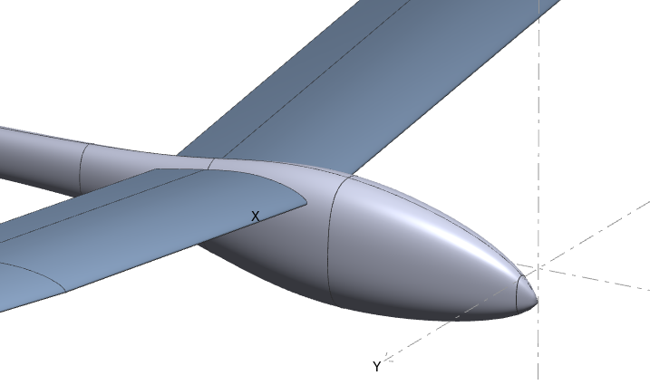
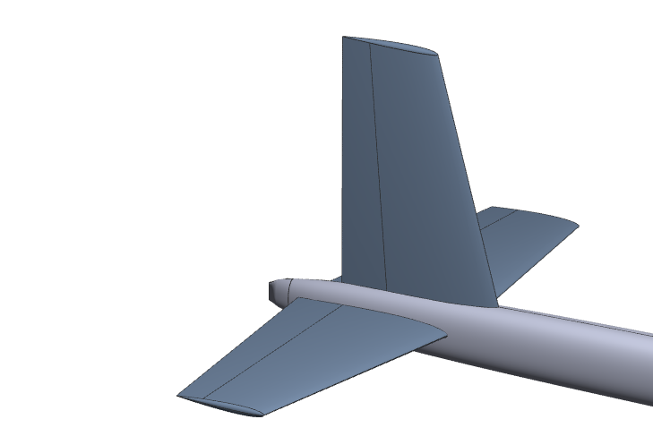
The important thing is to avoid partial intersections as illustrated in the figures on the right. Such configurations may have two consequences:
- they may cause the meshing operation of the fuselage to fail
- they cause the strips to skew excessively on the wings
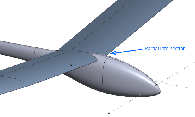
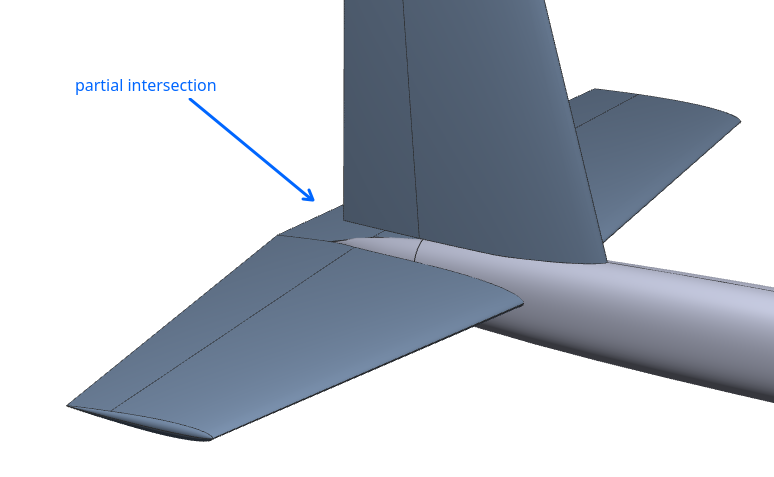
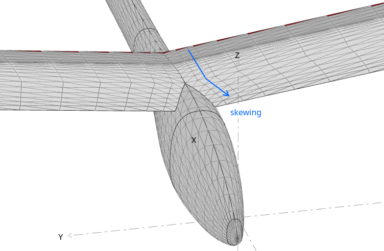
It is recommended in such case to modify the configuration to achieve full intersections, even if it means to deviate slightly from the plane's actual configuration.
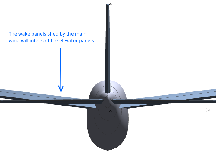
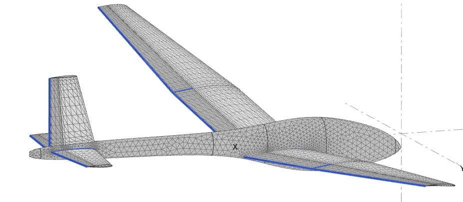
Positions of the wings in the vertical direction
The main issue to avoid is the intersection of wake panels with fuselage or wing panels.
Before running a panel analysis, flow5 will build wake panels shed from the wings' trailing edges and extending in straight lines in the x-direction. Typically, the wake panels shed by the upstream main wing may intersect the tail or fuselage panels. This may lead to unwanted numerical effects and incorrect results.
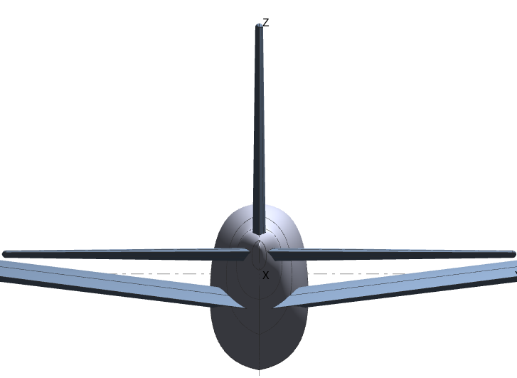
Note that the intersections should not occur also in the case of deflected trailing edge flaps.
These intersections should be avoided, even if it means to deviate slightly from the plane's actual configuration.
Back to top
Assembly and meshing
This step can be skipped if the fuselage is not included in the model.
If it is, the goal is to mesh the fuselage to make it compatible with the wing meshes.
The plane mesh can be constructed either for thin or thick surface calculations. The simplest and recommended method is to assemble it for thin surface calculations.
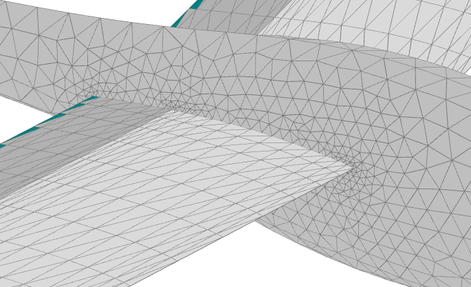
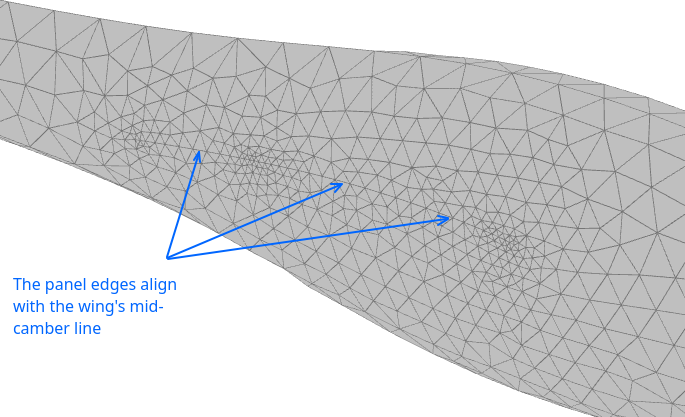
Thin surface assembly
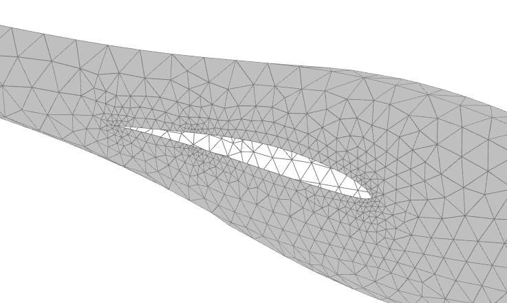
The goal is to mesh the fuselage so that element edges align with the wing panels located on the mid-camber line, as illustrated in the figures on the right.
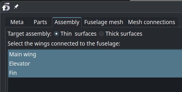
This is done
- by selecting "Thin assembly" in the plane editor third tab, then selecting those wing which connect to the fuselage;
- by moving on to the "Fuselage mesh" tab and requesting the mesh.
Thick surface assembly
The goal is to construct a mesh which will define one or more closed volumes.
Open volumes, i.e. non-watertight meshes, are not valid from the theoretical point of view.
To chieve this, fuselage mesh elements are constructed so that element edges align with the wing panels located on the top and bottom surfaces, as illustrated in the figures on the right.
This is done
- by selecting "Thick assembly" in the plane editor third tab, then selecting those wing which connect to the fuselage;
- by moving on to the "Fuselage mesh" tab and requesting the mesh.
Case of one-sided wings, e.g. fins
In the case of two-sided wings, flow5 leaves the inner surfaces opened by default so that the assembly of both half wings creates one volume.
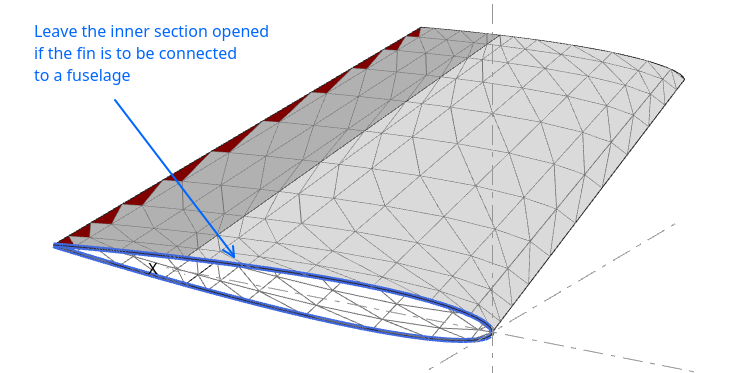
In the case of a one-sided wing, e.g. a fin, it's up to the user to define whether the inner surface should be closed or not, because flow5 doesn't know whether or not it is connected to the fuselage.
If it is connected, then the inner surface must be left left opened so as not to create elements inside the volume.
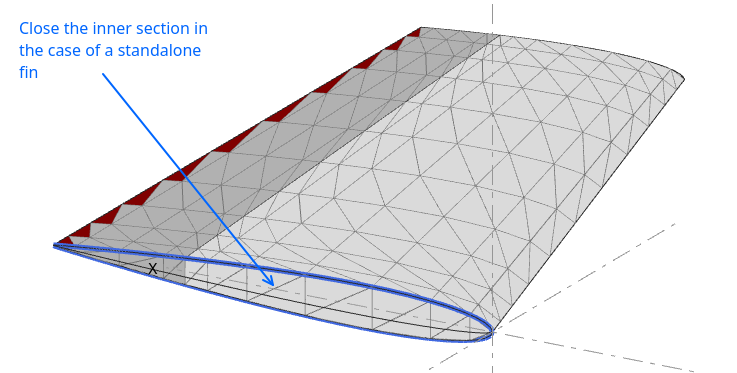
If it is not connected, for instance if the fuselage is not included, then the inner surface must be closed so that the fin is defined as an isolated closed volume.
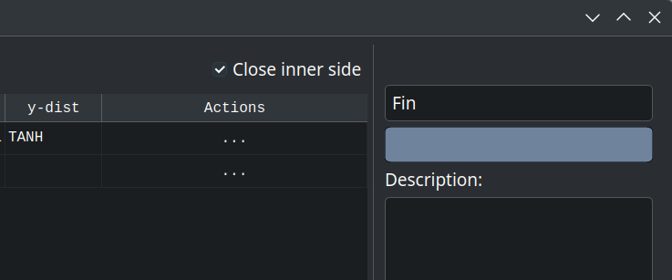
The option to close or leave opened is selected in the wing editor using the checkbox in the top right corner.
Back to top
Verification
The quality of the mesh can, and should, be verified a posteriori in a number of ways.
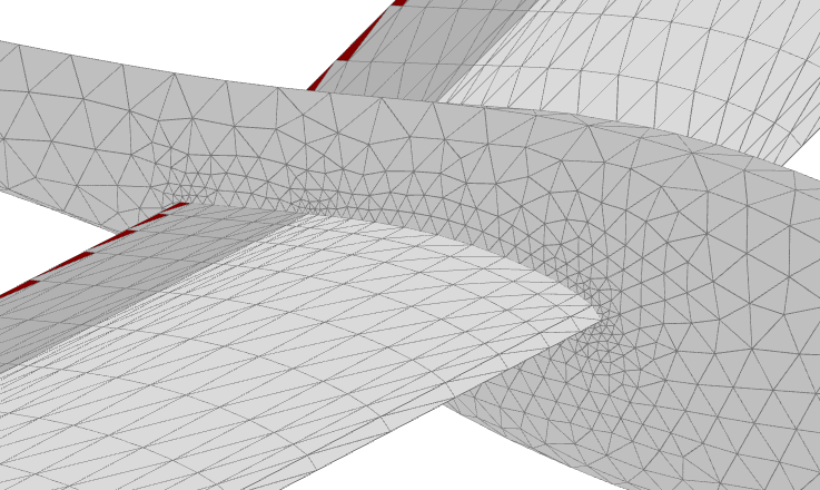
Free edges
Free edges can be visualized using the options in the plane's editor last tab by
- connecting the panels
- requesting the display of free edges
A free edge is a panel edge not connected to an adjacent triangle. Free edges should show up only at the wing's trailing edge, at the wing's root, and at the side of flaps.
Free edges at other locations may denote an opened mesh which should be corrected.
Wake panels
The wake panels can be visualized in the 3d view of the plane module once an analysis is selected.
Wake panels shed by upstream trailing edges should not intersect downstream meshpanels.
Doublet densities
The doublet densities, or the vortex circulations in the case of a VLM, are the direct result of a panel calculation. All other results are calculated using these doublet densities.
The doublet densities can be visualized in the 3d view of the plane module once an operating point is selected.
Mesh anamolies such as panel intersections show up as peaks of color, as illustrated on the right on the case of deflected flap intersections.
Such anomalies require manual correction of the mesh.
Back to top